Page 485 - Chemical process engineering design and economics
P. 485
462                                                      Chapter 8

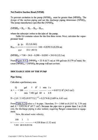
           Net Positive Suction Head (NPSH)

           To  prevent  cavitation  in the pump  (NPSH)A  must be  greater  than  (NPSH)R.  The
           design  of  the  suction  piping  and  not  the  discharge  piping  determines  (NPSH).
                                                                            A
           The pump manufacturer  specifies the (NPSH) R.
           (NPSH) A = H zi +  Hpi-Hps-HvPi

           where the subscript i refers to the inlet of  the pump.
                Table  8.6 contains values for the  first  three terms. Next, calculate the vapor-
           pressure head

                         32.2 (0.363)
                  g c  p v
           H Vp; = ——— = ——————     144 = 0.8393 ft (0.256 m)
                  g p    32.2  (62.3)

           (NPSH) A = 7.00 + 34.0 -  0.290 -  0.8393 = 39.9 ft (12.2 m)

           From Figure  8.4.2, (NPSH) = 22  ft (6.71 m) at  100 gal/min (0.379 m3/min). Be-
                                 R
           cause (NPSH) A > (NPSH) R the pump will not cavitate.


           DISCHARGE SIDE OF THE PUMP
           Pipe Sizing

           Calculate a preliminary area.

               Q       gal    1   ft 3  1  min  1 s
                                                           2
                                                                    2
           A = —  =  100  —— —————    ————   —— = 0.03713 ft  (34.5 cm )
               v       min  7.481  gal  60  s  6ft
                                   1/2
           D = [ (4 / 3.142) (0.03713) ]  = 0.2174 ft (2.609 in, 6.63 cm)
           From Table  8.2A select a 3 in pipe. Therefore,  D = 3.068 in (0.2557 ft, 7.79 cm)
                                    2
                           2
           and A  =  0.05136  ft  (47.7 cm ). Because  the pipe  size  is  greater  than  2  in (5.08
           cm),  the  discharge piping  is also welded, requiring  flanged  connections to  equip-
           ment.
                Now,  the actual water velocity,
               100   1    1
           v =  ———  —— ———— = 4.338 ft/sec (1.32 m/s)
              7.481  60.00.05136


         Copyright © 2003 by Taylor & Francis Group LLC

