Page 487 - Chemical process engineering design and economics
P. 487
464                                                       Chapter 8

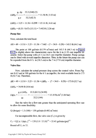
                 g c Ap  32.2 (144) (5)
                 = ——— = ———————    =  1 1 .56 ft ( 3.52 m)
            (AH) E
                  g p    32.2 (62.3)
            (AH)' F = 3.25 + 1 1.56 + 0.299  =  15.1 1 ft ( 4.61 m)


            (AH) V = (0.33 / 0.67) (15.11) = 7.442 ft ( 2.26 m)
           Pump Size

           Next, calculate the total head.

           AH = 49 + 1 15.0 + 3.25 + 1 1.56 + 7.442 -  (7 + 34.0 -  0.29) = 145.5 ft (44.3 m)

                                             3
                The  point  at  100  gal/min  (0.379  m /min)  and  145.5 ft (44.3 m)  in  Figure
            8.4.2  is slightly  above  the  characteristic curve  for the  6 in (1.52 cm)  impeller  di-
            ameter. Select the pump with a 6  1/2 in (16.5 cm) impeller diameter. Pump casings
            can be fitted with several impeller diameters. Thus, in the future  the pump size can
           be expanded from the 6  V4 in (16.5 cm) to the 7 in (17.8 cm) impeller diameter.

           Valve Size

                Now,  calculate the actual pressure drop across the control  valve. From Fig-
                                           1
           ure 8.4.2 and at  100 gal/min for the 6 A in impeller, the total available head is  173
            ft (52.7 m).  Therefore,
           AH = 49+115.0 + 3.25 + H.56 + (AH)v -  (7 + 34.0-  0.29)= 173.0 (52.7m)

            (AH) V = 34.90 ft (10.6m)


                  gp(AH) v   32.2 (62.3) (34.90)
                                                        2
            (Ap) v = ————— =  ——————————    =  15.10 lb F/in  (1.04 bar)
                                32.2 (144)
                     g c
                Size the valve for a flow rate greater than the anticipated operating flow rate
           to allow for some flexibility.
                                                3
           Q (design) = 1.3 (100) = 130 gal/min (0.492 m /min)

                For incompressible flow, the valve size (Cv) is given by
                                            172
                            1/2
           C v = Q [ r) / (Ap) v ]  = 130 (1.0 /  15.10)  = 33.45 gal/min-(psi) 1/2
           Round off C v to 33.


         Copyright © 2003 by Taylor & Francis Group LLC

