Page 488 - Chemical process engineering design and economics
P. 488

Design of Flow Systems                                        465


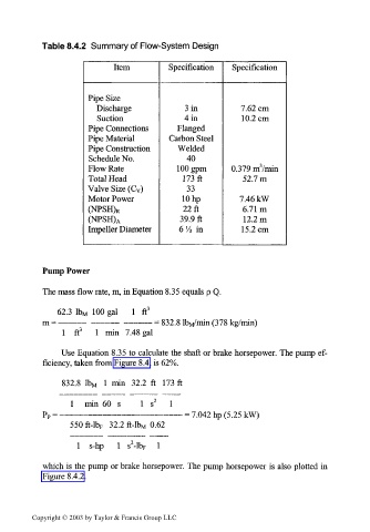
            Table 8.4.2  Summary of Flow-System  Design

                            Item         Specification  Specification


                      Pipe Size
                        Discharge           Sin          7.62 cm
                        Suction             4 in         10.2  cm
                      Pipe Connections     Flanged
                      Pipe Material      Carbon Steel
                      Pipe Construction    Welded
                      Schedule No.           40
                      Flow Rate            100 gpm     0.379 nrVmin
                      Total Head            173ft         52.7m
                      Valve Size (C v)       33
                      Motor Power           10 hp        7.46 kW
                      (NPSH) R              22ft          6.71m
                                           39.9ft         12.2m
                      (NPSH) A
                      Impeller Diameter    6  'A  in     15.2cm


            Pump Power

            The mass flow rate, m, in Equation 8.35 equals p Q.

               62.3  Ibw  100  gal  1  ft 3
            m  = -                   - =  832.8 IbM/min (378 kg/min)
                1  ft 3  1  min  7.48 gal

                Use Equation 8.35  to  calculate the  shaft  or brake horsepower. The pump ef-
            ficiency, taken from Figure 8.4, is 62%.
                832.8  lb M  1  min  32.2 ft  173  ft

                  1   min  60  s
                                            - = 7.042 hp (5.25 kW)
                  550 ft-lb F  32.2  ft-lb M  0.62
                                 2
                    1  s-hp  1  s -lb F  1
            which is the pump or brake horsepower. The  pump horsepower  is  also plotted  in
            Figure 8.4.2.


         Copyright © 2003 by Taylor & Francis Group LLC
   483   484   485   486   487   488   489   490   491   492   493