
Page 477 - Chemical process engineering design and economics
P. 477
Design of Flow Systems 455
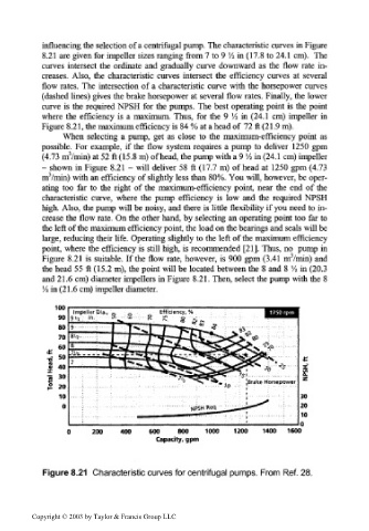
influencing the selection of a centrifugal pump. The characteristic curves in Figure
8.21 are given for impeller sizes ranging from 7 to 9 'A in (17.8 to 24.1 cm). The
curves intersect the ordinate and gradually curve downward as the flow rate in-
creases. Also, the characteristic curves intersect the efficiency curves at several
flow rates. The intersection of a characteristic curve with the horsepower curves
(dashed lines) gives the brake horsepower at several flow rates. Finally, the lower
curve is the required NPSH for the pumps. The best operating point is the point
1
where the efficiency is a maximum. Thus, for the 9 A in (24.1 cm) impeller in
Figure 8.21, the maximum efficiency is 84 % at a head of 72 ft (21.9 m).
When selecting a pump, get as close to the maximum-efficiency point as
possible. For example, if the flow system requires a pump to deliver 1250 gpm
3
(4.73 m /min) at 52 ft (15.8 m) of head, the pump with a 9 Vi in (24.1 cm) impeller
- shown in Figure 8.21 - will deliver 58 ft (17.7 m) of head at 1250 gpm (4.73
m3/min) with an efficiency of slightly less than 80%. You will, however, be oper-
ating too far to the right of the maximum-efficiency point, near the end of the
characteristic curve, where the pump efficiency is low and the required NPSH
high. Also, the pump will be noisy, and there is little flexibility if you need to in-
crease the flow rate. On the other hand, by selecting an operating point too far to
the left of the maximum efficiency point, the load on the bearings and seals will be
large, reducing their life. Operating slightly to the left of the maximum efficiency
point, where the efficiency is still high, is recommended [21]. Thus, no pump in
3
Figure 8.21 is suitable. If the flow rate, however, is 900 gpm (3.41 m /min) and
1
the head 55 ft (15.2 m), the point will be located between the 8 and 8 A in (20.3
and 21.6 cm) diameter impellers in Figure 8.21. Then, select the pump with the 8
'/•> in (21.6 cm) impeller diameter.
200 400 600 800 1000 1200 1400 1600
Capacity, gpm
Figure 8.21 Characteristic curves for centrifugal pumps. From Ref. 28.
Copyright © 2003 by Taylor & Francis Group LLC