
Page 478 - Chemical process engineering design and economics
P. 478
456 Chapter 8
Example 8.4 Centrifugal-Pump Sizing
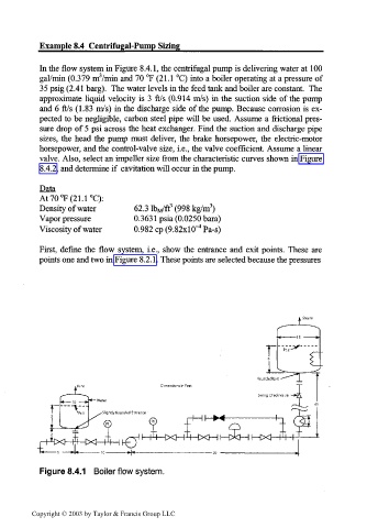
In the flow system in Figure 8.4.1, the centrifugal pump is delivering water at 100
gal/min (0.379 m3/min and 70 °F (21.1 °C) into a boiler operating at a pressure of
35 psig (2.41 barg). The water levels in the feed tank and boiler are constant. The
approximate liquid velocity is 3 ft/s (0.914 m/s) in the suction side of the pump
and 6 ft/s (1.83 m/s) in the discharge side of the pump. Because corrosion is ex-
pected to be negligible, carbon steel pipe will be used. Assume a frictional pres-
sure drop of 5 psi across the heat exchanger. Find the suction and discharge pipe
sizes, the head the pump must deliver, the brake horsepower, the electric-motor
horsepower, and the control-valve size, i.e., the valve coefficient. Assume a linear
valve. Also, select an impeller size from the characteristic curves shown in Figure
8.4.2, and determine if cavitation will occur in the pump.
Data
At70°F(21.1°C):
3
3
Density of water 62.3 lb M/ft (998 kg/m )
Vapor pressure 0.363 Ipsia (0.0250 bara)
Viscosity of water 0.982 cp (9.82x1 O^Pa-s)
First, define the flow system, i.e., show the entrance and exit points. These are
points one and two in Figure 8.2.1. These points are selected because the pressures
Figure 8.4.1 Boiler flow system.
Copyright © 2003 by Taylor & Francis Group LLC