Page 293 - Civil Engineering Formulas
P. 293

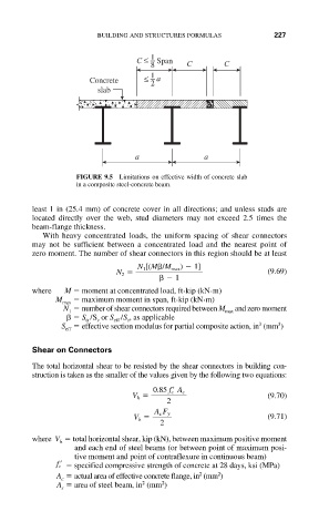
BUILDING AND STRUCTURES FORMULAS        227

                                    C ≤  1  Span
                                        8       C       C
                          Concrete    ≤  1  a
                                        2
                            slab


                                    a               a

                       FIGURE 9.5  Limitations on effective width of concrete slab
                       in a composite steel-concrete beam.

             least 1 in (25.4 mm) of concrete cover in all directions; and unless studs are
             located directly over the web, stud diameters may not exceed 2.5 times the
             beam-flange thickness.
               With heavy concentrated loads, the uniform spacing of shear connectors
             may not be sufficient between a concentrated load and the nearest point of
             zero moment. The number of shear connectors in this region should be at least
                                     N 1 [(M /M max )   1]
                                N 2                               (9.69)
                                             1
             where  M   moment at concentrated load, ft kip (kN m)
                  M max    maximum moment in span, ft kip (kN m)
                    N   number of shear connectors required between M max and zero moment
                     1
                        S /S or S /S , as applicable
                                  s
                         tr
                            s
                               eff
                                                                    3
                                                                3
                   S   effective section modulus for partial composite action, in (mm )
                    eff
             Shear on Connectors
             The total horizontal shear to be resisted by the shear connectors in building con-
             struction is taken as the smaller of the values given by the following two equations:
                                   V h    0.85 f c   A c          (9.70)
                                           2
                                        A s F y
                                    V h                           (9.71)
                                          2
             where V   total horizontal shear, kip (kN), between maximum positive moment
                   h
                      and each end of steel beams (or between point of maximum posi-
                      tive moment and point of contraflexure in continuous beam)
                  f c      specified compressive strength of concrete at 28 days, ksi (MPa)
                                                   2
                                                       2
                  A   actual area of effective concrete flange, in (mm )
                   c
                                      2
                                          2
                  A   area of steel beam, in (mm )
                   s
   288   289   290   291   292   293   294   295   296   297   298