
Page 289 - Civil Engineering Formulas
P. 289
BUILDING AND STRUCTURES FORMULAS 223
N
k
N + 5k
Toe of fillet
N + 2.5k
k
N
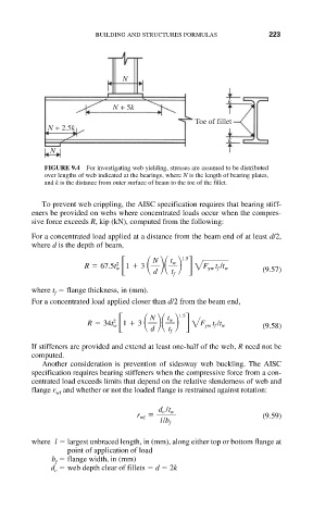
FIGURE 9.4 For investigating web yielding, stresses are assumed to be distributed
over lengths of web indicated at the bearings, where N is the length of bearing plates,
and k is the distance from outer surface of beam to the toe of the fillet.
To prevent web crippling, the AISC specification requires that bearing stiff-
eners be provided on webs where concentrated loads occur when the compres-
sive force exceeds R, kip (kN), computed from the following:
For a concentrated load applied at a distance from the beam end of at least d/2,
where d is the depth of beam,
R 67.5t w 1 3 N t w 1.5
2
2 F yw t f /t w
d t f (9.57)
where t flange thickness, in (mm).
f
For a concentrated load applied closer than d/2 from the beam end,
R 34t w 1 3 N t w 1.5
2
2 F yw t f /t w
d t f (9.58)
If stiffeners are provided and extend at least one-half of the web, R need not be
computed.
Another consideration is prevention of sidesway web buckling. The AISC
specification requires bearing stiffeners when the compressive force from a con-
centrated load exceeds limits that depend on the relative slenderness of web and
flange r and whether or not the loaded flange is restrained against rotation:
wf
r wf d c /t w (9.59)
l / b f
where l largest unbraced length, in (mm), along either top or bottom flange at
point of application of load
b flange width, in (mm)
f
d web depth clear of fillets d 2k
c