
Page 379 - Complete Wireless Design
P. 379
Support Circuit Design
378 Chapter Eight
8.8.2 Directional coupler design
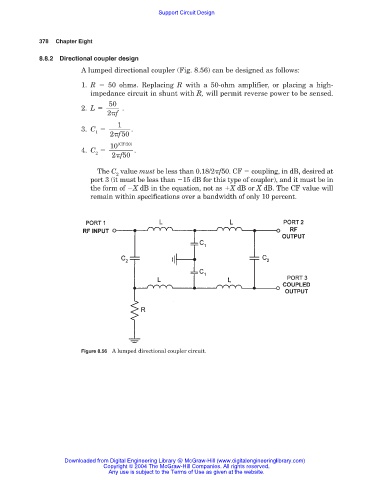
A lumped directional coupler (Fig. 8.56) can be designed as follows:
1. R 50 ohms. Replacing R with a 50-ohm amplifier, or placing a high-
impedance circuit in shunt with R, will permit reverse power to be sensed.
50
2. L .
2 f
1
3. C .
1
2 f50
10 (CF/20)
4. C .
2
2 f50
The C value must be less than 0.18/2 f50. CF coupling, in dB, desired at
2
port 3 (it must be less than 15 dB for this type of coupler), and it must be in
the form of X dB in the equation, not as X dB or X dB. The CF value will
remain within specifications over a bandwidth of only 10 percent.
Figure 8.56 A lumped directional coupler circuit.
Downloaded from Digital Engineering Library @ McGraw-Hill (www.digitalengineeringlibrary.com)
Copyright © 2004 The McGraw-Hill Companies. All rights reserved.
Any use is subject to the Terms of Use as given at the website.