
Page 378 - Complete Wireless Design
P. 378
Support Circuit Design
Support Circuit Design 377
8.8 Directional Couplers
8.8.1 Introduction
Directional couplers are 50-ohm devices constructed to allow an RF signal to
pass from the coupler’s input port through to its output port (called the main-
line of the coupler) with minimum insertion loss, while permitting a small part
of this signal (20, 10, or 6 dB less than the coupler’s mainline output) to be
tapped. The tapped signal can be a sample from the forward (incident) signal
that was injected into the coupler’s input, or it may be the power from any
reflected wave present from the device’s output port, depending on the cou-
pler’s orientation (Fig. 8.54). There are also dual directional couplers that will
measure both the forward and reverse power simultaneously through two sep-
arate ports.
Since the directional coupler taps only a small amount of power from the
mainline, as mentioned above, it subtracts very little power from the output of
the coupler. But most couplers are relatively narrowband, and must be chosen
or designed with a certain frequency range in mind.
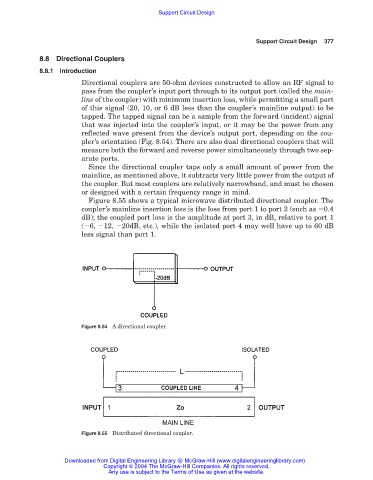
Figure 8.55 shows a typical microwave distributed directional coupler. The
coupler’s mainline insertion loss is the loss from port 1 to port 2 (such as 0.4
dB); the coupled port loss is the amplitude at port 3, in dB, relative to port 1
( 6, 12, 20dB, etc.), while the isolated port 4 may well have up to 60 dB
less signal than port 1.
Figure 8.54 A directional coupler.
Figure 8.55 Distributed directional coupler.
Downloaded from Digital Engineering Library @ McGraw-Hill (www.digitalengineeringlibrary.com)
Copyright © 2004 The McGraw-Hill Companies. All rights reserved.
Any use is subject to the Terms of Use as given at the website.