
Page 376 - Complete Wireless Design
P. 376
Support Circuit Design
Support Circuit Design 375
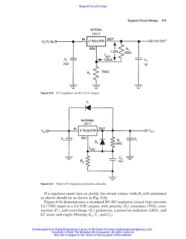
Figure 8.50 3-T regulator set for 5.5-V output.
Figure 8.51 Other 3-T regulator protection circuits.
If a regulator must turn on slowly, the circuit values (with R still calculated
2
as above) should be as shown in Fig. 8.52.
Figure 8.53 demonstrates a standard DC-DC regulator circuit that converts
13.7 VDC input to a 5.5 VDC output, with polarity (D ), transient (TVS), over-
2
current (F ), and overvoltage (D ) protection, a power-on indicator (LED), and
1 1
LC noise and ripple filtering (L , C , and C ).
1 1 2
Downloaded from Digital Engineering Library @ McGraw-Hill (www.digitalengineeringlibrary.com)
Copyright © 2004 The McGraw-Hill Companies. All rights reserved.
Any use is subject to the Terms of Use as given at the website.