
Page 375 - Complete Wireless Design
P. 375
Support Circuit Design
374 Chapter Eight
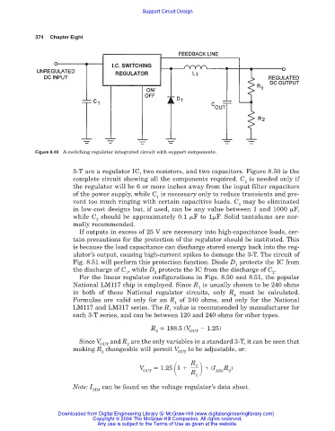
Figure 8.49 A switching regulator integrated circuit with support components.
3-T are a regulator IC, two resistors, and two capacitors. Figure 8.50 is the
complete circuit showing all the components required. C is needed only if
2
the regulator will be 6 or more inches away from the input filter capacitors
of the power supply, while C is necessary only to reduce transients and pre-
1
vent too much ringing with certain capacitive loads. C may be eliminated
1
in low-cost designs but, if used, can be any value between 1 and 1000 F,
while C should be approximately 0.1 F to 1 F. Solid tantalums are nor-
2
mally recommended.
If outputs in excess of 25 V are necessary into high-capacitance loads, cer-
tain precautions for the protection of the regulator should be instituted. This
is because the load capacitance can discharge stored energy back into the reg-
ulator’s output, causing high-current spikes to damage the 3-T. The circuit of
Fig. 8.51 will perform this protection function. Diode D protects the IC from
1
the discharge of C , while D protects the IC from the discharge of C .
1 2 2
For the linear regulator configurations in Figs. 8.50 and 8.51, the popular
National LM117 chip is employed. Since R is usually chosen to be 240 ohms
1
in both of these National regulator circuits, only R must be calculated.
2
Formulas are valid only for an R of 240 ohms, and only for the National
1
LM117 and LM317 series. The R value is recommended by manufacturer for
1
each 3-T series, and can be between 120 and 240 ohms for other types.
R 188.5 (V 1.25)
2 OUT
Since V and R are the only variables in a standard 3-T, it can be seen that
OUT 2
making R changeable will permit V to be adjustable, or:
2 OUT
R
2
V 1.25 1 (I R )
OUT R ADJ 2
1
Note: I can be found on the voltage regulator’s data sheet.
ADJ
Downloaded from Digital Engineering Library @ McGraw-Hill (www.digitalengineeringlibrary.com)
Copyright © 2004 The McGraw-Hill Companies. All rights reserved.
Any use is subject to the Terms of Use as given at the website.