
Page 370 - Complete Wireless Design
P. 370
Support Circuit Design
Support Circuit Design 369
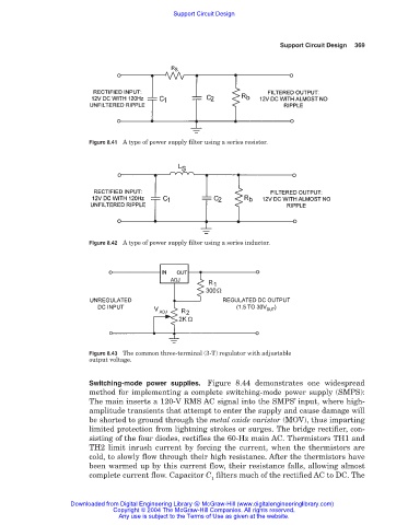
Figure 8.41 A type of power supply filter using a series resistor.
Figure 8.42 A type of power supply filter using a series inductor.
Figure 8.43 The common three-terminal (3-T) regulator with adjustable
output voltage.
Switching-mode power supplies. Figure 8.44 demonstrates one widespread
method for implementing a complete switching-mode power supply (SMPS):
The main inserts a 120-V RMS AC signal into the SMPS’ input, where high-
amplitude transients that attempt to enter the supply and cause damage will
be shorted to ground through the metal oxide varistor (MOV), thus imparting
limited protection from lightning strokes or surges. The bridge rectifier, con-
sisting of the four diodes, rectifies the 60-Hz main AC. Thermistors TH1 and
TH2 limit inrush current by forcing the current, when the thermistors are
cold, to slowly flow through their high resistance. After the thermistors have
been warmed up by this current flow, their resistance falls, allowing almost
complete current flow. Capacitor C filters much of the rectified AC to DC. The
1
Downloaded from Digital Engineering Library @ McGraw-Hill (www.digitalengineeringlibrary.com)
Copyright © 2004 The McGraw-Hill Companies. All rights reserved.
Any use is subject to the Terms of Use as given at the website.