
Page 369 - Complete Wireless Design
P. 369
Support Circuit Design
368 Chapter Eight
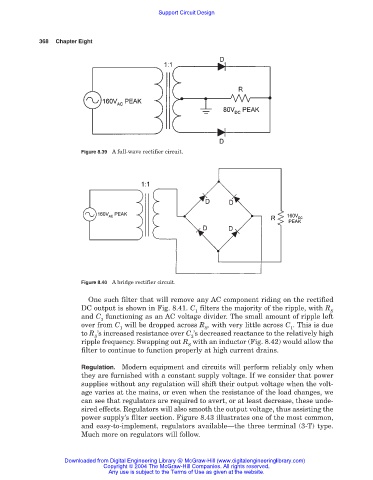
Figure 8.39 A full-wave rectifier circuit.
Figure 8.40 A bridge rectifier circuit.
One such filter that will remove any AC component riding on the rectified
DC output is shown in Fig. 8.41. C filters the majority of the ripple, with R
1 S
and C functioning as an AC voltage divider. The small amount of ripple left
2
over from C will be dropped across R , with very little across C . This is due
1 S 1
to R ’s increased resistance over C ’s decreased reactance to the relatively high
S 2
ripple frequency. Swapping out R with an inductor (Fig. 8.42) would allow the
S
filter to continue to function properly at high current drains.
Regulation. Modern equipment and circuits will perform reliably only when
they are furnished with a constant supply voltage. If we consider that power
supplies without any regulation will shift their output voltage when the volt-
age varies at the mains, or even when the resistance of the load changes, we
can see that regulators are required to avert, or at least decrease, these unde-
sired effects. Regulators will also smooth the output voltage, thus assisting the
power supply’s filter section. Figure 8.43 illustrates one of the most common,
and easy-to-implement, regulators available—the three terminal (3-T) type.
Much more on regulators will follow.
Downloaded from Digital Engineering Library @ McGraw-Hill (www.digitalengineeringlibrary.com)
Copyright © 2004 The McGraw-Hill Companies. All rights reserved.
Any use is subject to the Terms of Use as given at the website.