
Page 368 - Complete Wireless Design
P. 368
Support Circuit Design
Support Circuit Design 367
being a bleeder resistor that drains a fixed current from the regulator to help
stabilize the output voltage, as well as drain hazardous voltage levels from the
filter capacitors when the power supply is shut off. More on each of these cir-
cuits below.
Transformer. Since a transformer conveys AC energy from one circuit to
another by electromagnetic induction, we can increase or decrease the current
or voltage by changing the ratio of the windings between the primary and the
secondary. A low-frequency transformer is made up of a primary coil, which
obtains energy from an alternating current source. The primary’s expanding
and contracting magnetic flux lines flow through a core made of steel plates,
which concentrates this flux with the least amount of losses. The primary’s
flux lines cut the secondary coil, inducing an AC voltage and producing a cur-
rent that flows through the transformer’s load.
Rectification. Rectification is the first step in obtaining a smooth DC output
voltage. AC power can be changed into pulsating DC by employing one of three
general rectification circuits.
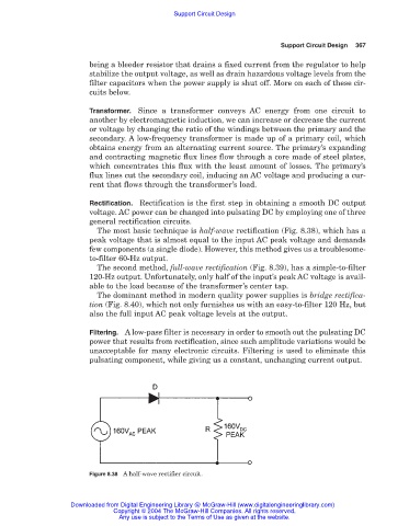
The most basic technique is half-wave rectification (Fig. 8.38), which has a
peak voltage that is almost equal to the input AC peak voltage and demands
few components (a single diode). However, this method gives us a troublesome-
to-filter 60-Hz output.
The second method, full-wave rectification (Fig. 8.39), has a simple-to-filter
120-Hz output. Unfortunately, only half of the input’s peak AC voltage is avail-
able to the load because of the transformer’s center tap.
The dominant method in modern quality power supplies is bridge rectifica-
tion (Fig. 8.40), which not only furnishes us with an easy-to-filter 120 Hz, but
also the full input AC peak voltage levels at the output.
Filtering. A low-pass filter is necessary in order to smooth out the pulsating DC
power that results from rectification, since such amplitude variations would be
unacceptable for many electronic circuits. Filtering is used to eliminate this
pulsating component, while giving us a constant, unchanging current output.
Figure 8.38 A half-wave rectifier circuit.
Downloaded from Digital Engineering Library @ McGraw-Hill (www.digitalengineeringlibrary.com)
Copyright © 2004 The McGraw-Hill Companies. All rights reserved.
Any use is subject to the Terms of Use as given at the website.