
Page 371 - Complete Wireless Design
P. 371
Support Circuit Design
370 Chapter Eight
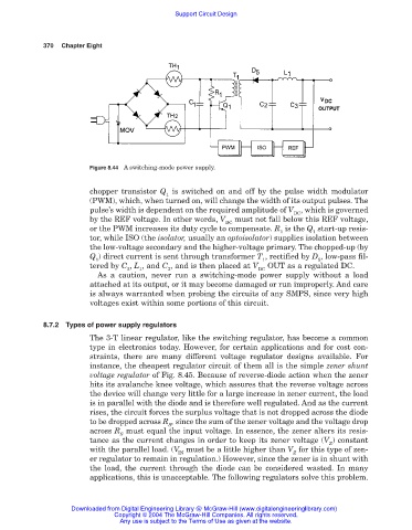
Figure 8.44 A switching-mode power supply.
chopper transistor Q is switched on and off by the pulse width modulator
1
(PWM), which, when turned on, will change the width of its output pulses. The
pulse’s width is dependent on the required amplitude of V , which is governed
DC
by the REF voltage. In other words, V must not fall below this REF voltage,
DC
or the PWM increases its duty cycle to compensate. R is the Q start-up resis-
1 1
tor, while ISO (the isolator, usually an optoisolator) supplies isolation between
the low-voltage secondary and the higher-voltage primary. The chopped-up (by
Q ) direct current is sent through transformer T , rectified by D , low-pass fil-
1 1 5
tered by C , L , and C , and is then placed at V OUT as a regulated DC.
2 1 3 DC
As a caution, never run a switching-mode power supply without a load
attached at its output, or it may become damaged or run improperly. And care
is always warranted when probing the circuits of any SMPS, since very high
voltages exist within some portions of this circuit.
8.7.2 Types of power supply regulators
The 3-T linear regulator, like the switching regulator, has become a common
type in electronics today. However, for certain applications and for cost con-
straints, there are many different voltage regulator designs available. For
instance, the cheapest regulator circuit of them all is the simple zener shunt
voltage regulator of Fig. 8.45. Because of reverse-diode action when the zener
hits its avalanche knee voltage, which assures that the reverse voltage across
the device will change very little for a large increase in zener current, the load
is in parallel with the diode and is therefore well regulated. And as the current
rises, the circuit forces the surplus voltage that is not dropped across the diode
to be dropped across R , since the sum of the zener voltage and the voltage drop
S
across R must equal the input voltage. In essence, the zener alters its resis-
S
tance as the current changes in order to keep its zener voltage (V ) constant
Z
with the parallel load. (V must be a little higher than V for this type of zen-
IN Z
er regulator to remain in regulation.) However, since the zener is in shunt with
the load, the current through the diode can be considered wasted. In many
applications, this is unacceptable. The following regulators solve this problem.
Downloaded from Digital Engineering Library @ McGraw-Hill (www.digitalengineeringlibrary.com)
Copyright © 2004 The McGraw-Hill Companies. All rights reserved.
Any use is subject to the Terms of Use as given at the website.