
Page 45 - Complete Wireless Design
P. 45
Wireless Essentials
44 Chapter One
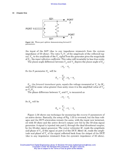
Figure 1.54 Three-port splitter demonstrating forward S
parameters.
the input of the BJT (due to any impedance mismatch from the system
impedance of 50 ohms). The ratio V /V of the amplitude of the reflected sig-
B A
nal, V , to the amplitude of the V signal from the generator gives the magnitude
B A
of S , the input reflection coefficient. This value will invariably be less than unity.
11
The phase angle difference between V and V depicts the phase angle of S :
B A 11
B A
So the S parameter S will be
11
V
B
S
11 V B A
A
S , the forward transducer gain, equals the voltage measured at V by M ,
21 C 3
and will be some value greater than unity since it is the amplified value of V ,
A
or V /V .
C A
The phase difference between V and V is measured as
C A
C A
So S will be
21
V
C
S
21 V C A
A
Figure 1.56 shows one technique for measuring the reverse S parameters of
an active device. Basically, the setup of Fig. 1.55 is reversed, but the bias volt-
ages and the DUT orientation remain the same, with the input now terminat-
ed with 50 ohms and the active device’s output now fed by the 50-ohm signal
generator. A signal is injected into port 2, through the dual directional coupler,
by the 50-ohm signal generator. The vector voltmeter M reads the amplitude
4
and phase of V of the signal at port 2 of the DUT. Meter M reads the ampli-
D 3
tude and phase of V of the signal reflected back from the output of the DUT
C
(due to any impedance mismatch from the system’s impedance of 50 ohms).
Downloaded from Digital Engineering Library @ McGraw-Hill (www.digitalengineeringlibrary.com)
Copyright © 2004 The McGraw-Hill Companies. All rights reserved.
Any use is subject to the Terms of Use as given at the website.