
Page 42 - Complete Wireless Design
P. 42
Wireless Essentials
Wireless Essentials 41
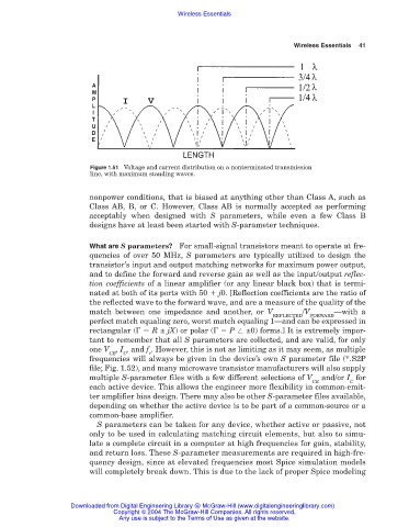
Figure 1.51 Voltage and current distribution on a nonterminated transmission
line, with maximum standing waves.
nonpower conditions, that is biased at anything other than Class A, such as
Class AB, B, or C. However, Class AB is normally accepted as performing
acceptably when designed with S parameters, while even a few Class B
designs have at least been started with S-parameter techniques.
What are S parameters? For small-signal transistors meant to operate at fre-
quencies of over 50 MHz, S parameters are typically utilized to design the
transistor’s input and output matching networks for maximum power output,
and to define the forward and reverse gain as well as the input/output reflec-
tion coefficients of a linear amplifier (or any linear black box) that is termi-
nated at both of its ports with 50 j0. [Reflection coefficients are the ratio of
the reflected wave to the forward wave, and are a measure of the quality of the
match between one impedance and another, or V /V —with a
REFLECTED FORWARD
perfect match equaling zero, worst match equaling 1—and can be expressed in
rectangular ( R ± jX) or polar ( P ±0) forms.] It is extremely impor-
tant to remember that all S parameters are collected, and are valid, for only
one V , I , and f . However, this is not as limiting as it may seem, as multiple
CE C r
frequencies will always be given in the device’s own S parameter file (*.S2P
file; Fig. 1.52), and many microwave transistor manufacturers will also supply
multiple S-parameter files with a few different selections of V and/or I for
CE C
each active device. This allows the engineer more flexibility in common-emit-
ter amplifier bias design. There may also be other S-parameter files available,
depending on whether the active device is to be part of a common-source or a
common-base amplifier.
S parameters can be taken for any device, whether active or passive, not
only to be used in calculating matching circuit elements, but also to simu-
late a complete circuit in a computer at high frequencies for gain, stability,
and return loss. These S-parameter measurements are required in high-fre-
quency design, since at elevated frequencies most Spice simulation models
will completely break down. This is due to the lack of proper Spice modeling
Downloaded from Digital Engineering Library @ McGraw-Hill (www.digitalengineeringlibrary.com)
Copyright © 2004 The McGraw-Hill Companies. All rights reserved.
Any use is subject to the Terms of Use as given at the website.