
Page 39 - Complete Wireless Design
P. 39
Wireless Essentials
38 Chapter One
1.4 Transmission Lines
1.4.1 Introduction
Transmission lines are conductors intended to move current from one location
to another not only without radiating, but also at a selected impedance. There
are two kinds of lumped RF transmission lines: unbalanced, normally in the
form of coaxial cable, and balanced, such as twin-lead.
Waveguide, a type of transmission line, can still be found in high-powered
microwave transmitters, but is normally more expensive than coaxial cable
and is much harder to work with.
1.4.2 Transmission line types
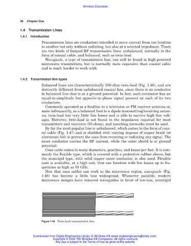
Balanced lines are characteristically 300-ohm twin-lead (Fig. 1.46), and are
distinctly different from unbalanced coaxial line, since there is no conductor
in balanced line that is at a ground potential. In fact, each conductor has an
equal-in-amplitude but opposite-in-phase signal present on each of its two
conductors.
Commonly operated as a feedline to a television or FM receiver antenna or,
more infrequently, as a balanced feed to a dipole transmitting/receiving anten-
na, twin-lead has very little line losses and is able to survive high line volt-
ages. However, twin-lead is not found in the impedance required for most
transmitters and receivers (50 ohms), and matching networks must be used.
By far the most popular line is unbalanced, which comes in the form of coax-
ial cable (Fig. 1.47) and is shielded with varying degrees of copper braid (or
aluminum foil) to prevent the coax from receiving or radiating any signal. The
inner conductor carries the RF current, while the outer shield is at ground
potential.
Coax cable comes in many diameters, qualities, and losses per foot. It is com-
monly the flexible type, which is covered with a protective rubber sleeve, but
the semirigid type, with solid copper outer conductor, is also used. Flexible
coax is available, at a high cost, that can function with low losses up to fre-
quencies as high as 50 GHz.
Now that coax cables can work in the microwave region, waveguide (Fig.
1.48) has become a little less widespread. Whenever possible, modern
microwave designs have removed waveguides in favor of low-loss, semirigid
Figure 1.46 Twin-lead transmission line.
Downloaded from Digital Engineering Library @ McGraw-Hill (www.digitalengineeringlibrary.com)
Copyright © 2004 The McGraw-Hill Companies. All rights reserved.
Any use is subject to the Terms of Use as given at the website.