
Page 38 - Complete Wireless Design
P. 38
Wireless Essentials
Wireless Essentials 37
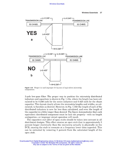
Figure 1.45 Proper (a) and improper (b) layouts of equivalent microstrip
components.
3-pole low-pass filter. The proper way to position the microstrip distributed
inductors and capacitors is shown in Fig. 1.45a, where the length has been cal-
culated to be 0.246 inch for the series inductors and 0.425 inch for the shunt
capacitor. This layout clearly allows the microstrip lengths and widths, as cal-
culated, to function as desired. However, in Fig. 1.45b the length of each of the
distributed inductors is now far less than calculated, and even the length of
the capacitor is a little longer than desired. The figure demonstrates that each
equivalent distributed component must be laid out properly—with no length
ambiguities—or improper circuit operation will result.
The capacitive end effect of open stubs should be taken into account in all
distributed designs. This effect creates an open stub that is approximately 5
percent longer electrically than the microstrip actually is physically on the
PCB, causing the stub to resonate at a frequency lower than expected. This
can be corrected by removing 5 percent from the calculated length of the
open stub.
Downloaded from Digital Engineering Library @ McGraw-Hill (www.digitalengineeringlibrary.com)
Copyright © 2004 The McGraw-Hill Companies. All rights reserved.
Any use is subject to the Terms of Use as given at the website.