
Page 33 - Complete Wireless Design
P. 33
Wireless Essentials
32 Chapter One
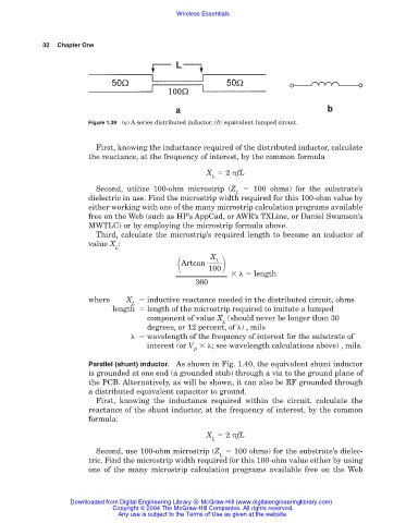
Figure 1.39 (a) A series distributed inductor; (b) equivalent lumped circuit.
First, knowing the inductance required of the distributed inductor, calculate
the reactance, at the frequency of interest, by the common formula
X 2 fL
L
Second, utilize 100-ohm microstrip (Z 100 ohms) for the substrate’s
L
dielectric in use. Find the microstrip width required for this 100-ohm value by
either working with one of the many microstrip calculation programs available
free on the Web (such as HP’s AppCad, or AWR’s TXLine, or Daniel Swanson’s
MWTLC) or by employing the microstrip formula above.
Third, calculate the microstrip’s required length to become an inductor of
value X :
L
Artcan
X
L
100
length
360
where X inductive reactance needed in the distributed circuit, ohms
L
length length of the microstrip required to imitate a lumped
component of value X (should never be longer than 30
L
degrees, or 12 percent, of ) , mils
wavelength of the frequency of interest for the substrate of
interest (or V ; see wavelength calculations above) , mils.
P
Parallel (shunt) inductor. As shown in Fig. 1.40, the equivalent shunt inductor
is grounded at one end (a grounded stub) through a via to the ground plane of
the PCB. Alternatively, as will be shown, it can also be RF grounded through
a distributed equivalent capacitor to ground.
First, knowing the inductance required within the circuit, calculate the
reactance of the shunt inductor, at the frequency of interest, by the common
formula:
X 2 fL
L
Second, use 100-ohm microstrip (Z 100 ohms) for the substrate’s dielec-
L
tric. Find the microstrip width required for this 100-ohm value either by using
one of the many microstrip calculation programs available free on the Web
Downloaded from Digital Engineering Library @ McGraw-Hill (www.digitalengineeringlibrary.com)
Copyright © 2004 The McGraw-Hill Companies. All rights reserved.
Any use is subject to the Terms of Use as given at the website.