
Page 32 - Complete Wireless Design
P. 32
Wireless Essentials
Wireless Essentials 31
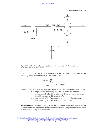
Figure 1.38 (a) A distributed capacitor; (b) two shunts equaling the single capacitor; (c)
equivalent lumped shunt capacitor.
Third, calculate the required microstrip’s length to become a capacitor of
value X , as calculated above, with this formula:
c
Arctan
30
X
c
length
360
where X capacitive reactance required in the distributed circuit, ohms
c
length length of the microstrip required to imitate a lumped
component of value X in mils (which should never be longer
c
than 30 degrees, or 12 percent, of )
wavelength of the frequency of interest for the substrate of
interest (or V ; see above formulas) , mils
P
Series inductor. As shown in Fig. 1.39, the equivalent series inductor is placed
in series with the 50-ohm microstrip transmission line, or placed between other
distributed or lumped components.
Downloaded from Digital Engineering Library @ McGraw-Hill (www.digitalengineeringlibrary.com)
Copyright © 2004 The McGraw-Hill Companies. All rights reserved.
Any use is subject to the Terms of Use as given at the website.