
Page 37 - Complete Wireless Design
P. 37
Wireless Essentials
36 Chapter One
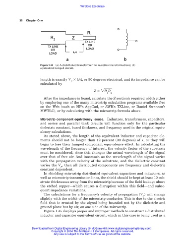
Figure 1.44 (a) A distributed transformer for resistive transformations; (b)
equivalent lumped circuit.
length is exactly V /4, or 90 degrees electrical, and its impedance can be
P
calculated by
Z R R
1 2
After the impedance is found, calculate the Z section’s required width either
by employing one of the many microstrip calculation programs available free
on the Web (such as HP’s AppCad, or AWR’s TXLine, or Daniel Swanson’s
MWTLC), or by calculating with the microstrip formula above.
Microstrip component equivalency issues. Inductors, transformers, capacitors,
and series and parallel tank circuits will function only for the particular
dielectric constant, board thickness, and frequency used in the original equiv-
alency calculations.
As stated above, the length of the equivalent inductor and capacitor ele-
ments should not be longer than 12 percent (30 degrees) of , or they will
begin to lose their lumped component equivalence effect. In calculating the
wavelength of the frequency of interest, the velocity factor of the substrate
must be considered, since this changes the actual wavelength of the signal
over that of free air. And inasmuch as the wavelength of the signal varies
with the propagation velocity of the substrate, and the dielectric constant
varies the V , then all distributed components are frequency and dielectric
P
constant dependent.
In shielding microstrip distributed equivalent capacitors and inductors, as
well as microstrip transmission lines, the shield should be kept at least 10 sub-
strate thicknesses away from the microstrip because of the field leakage above
the etched copper—which causes a disruption within this field—and subse-
quent impedance variations.
The calculations for a frequency’s velocity of propagation (V ) will change
P
slightly with the width of the microstrip conductor. This is due to the electric
field that is created by the signal being bounded not by the dielectric and
ground plane but by air, on one side of the microstrip.
Figure 1.45 displays proper and improper methods to construct a distributed
inductor and capacitor equivalent circuit, which in this case is being used as a
Downloaded from Digital Engineering Library @ McGraw-Hill (www.digitalengineeringlibrary.com)
Copyright © 2004 The McGraw-Hill Companies. All rights reserved.
Any use is subject to the Terms of Use as given at the website.