
Page 40 - Complete Wireless Design
P. 40
Wireless Essentials
Wireless Essentials 39
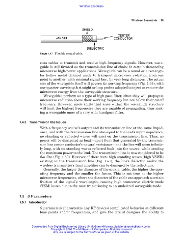
Figure 1.47 Flexible coaxial cable.
coax cables to transmit and receive high-frequency signals. However, wave-
guide is still favored as the transmission line of choice in certain demanding
microwave high-power applications. Waveguide can be a round or a rectangu-
lar hollow metal channel made to transport microwave radiation from one
point to another, with minimal signal loss, for very long distances. The actual
size of the waveguide itself will govern its working frequency (Fig. 1.49), with
one-quarter wavelength straight or loop probes adopted to inject or remove the
microwave energy from the waveguide structure.
Waveguides perform as a type of high-pass filter, since they will propagate
microwave radiation above their working frequency but not below their cutoff
frequency. However, mode shifts that arise within the waveguide structure
will limit the highest frequencies they are capable of propagating, thus mak-
ing a waveguide more of a very wide bandpass filter.
1.4.3 Transmission line issues
With a frequency source’s output and its transmission line at the same imped-
ance, and with the transmission line also equal to the load’s input impedance,
no standing or reflected waves will exist on the transmission line. Thus, no
power will be dissipated as heat—apart from that generated by the transmis-
sion line center conductor’s natural resistance—and the line will seem infinite-
ly long, with no standing waves reflected back into the source, while sending
the maximum power to the load. The transmission line is now considered to be
flat line (Fig. 1.50). However, if there were high standing waves (high VSWR)
existing on the transmission line (Fig. 1.51), the line’s dielectric and/or the
wireless transmitter’s final amplifier can be damaged by the reflections.
Generally, the larger the diameter of the coaxial cable, the higher the oper-
ating frequency and the smaller the losses. This is not true at the higher
microwave frequencies, where the diameter of the cable can approach a certain
fraction of the signal’s wavelength, causing high transverse electric mode
(TEM) losses due to the coax transitioning to an undesired waveguide mode.
1.5 S Parameters
1.5.1 Introduction
S parameters characterize any RF device’s complicated behavior at different
bias points and/or frequencies, and give the circuit designer the ability to
Downloaded from Digital Engineering Library @ McGraw-Hill (www.digitalengineeringlibrary.com)
Copyright © 2004 The McGraw-Hill Companies. All rights reserved.
Any use is subject to the Terms of Use as given at the website.