
Page 44 - Complete Wireless Design
P. 44
Wireless Essentials
Wireless Essentials 43
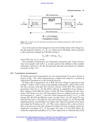
Figure 1.53 A 2-port network showing transmission and reflection parameters. DUT stands for
device under test.
As it is far easier for the designer to deal with decibels than with voltage lev-
els, the majority of the S , S , S , S values are in dB which, when compared
21 11 12 22
to the measured voltages in a 50-ohm system is
S (dB) 20 log |S |
XX 10 XX
where XX is 21, 12, 11, or 22.
Even though S parameters are frequently associated with 2-port devices,
they work equally well with 3, 4, or more ports by the addition of the suitable
subscripts, such as S for the forward gain through one branch of a splitter,
31
as shown in Fig. 1.54.
1.5.2 S parameter measurement
To clarify just what S parameters are, the measurement of an active device is
shown in Fig. 1.55, which demonstrates a simple test setup for a method of
taking the S parameters in the forward direction.
To obtain the S parameters for a BJT, the bias voltage is injected at bias
voltage 1 (with L and C acting as decoupling components), which will control
the base current, and thus the collector current, of the BJT. The emitter is
grounded, while the V for the BJT’s collector is supplied by bias voltage 2.
CE
Bias voltage 2 furnishes the Class A static DC bias conditions for the tran-
sistor. This hints as to why all S-parameter files are supplied only for a spe-
cific frequency, I , and V —and why other frequencies and I ’s or V ’s will
C CE C CE
change the device’s parameters (more on this later). An AC signal is now
injected into port 1, through the dual directional coupler, by the 50-ohm RF
signal generator (S parameters are taken only when terminated at the input
and output by 50 ohms, or 50 j0). The vector voltmeter M , a device that is
1
able to measure not only the voltage of a signal, but also its phase, reads the
amplitude and phase of V of the signal into port 1 of the BJT. Meter M
A 2
reads the amplitude and phase of V of the signal that is reflected back from
B
Downloaded from Digital Engineering Library @ McGraw-Hill (www.digitalengineeringlibrary.com)
Copyright © 2004 The McGraw-Hill Companies. All rights reserved.
Any use is subject to the Terms of Use as given at the website.