
Page 34 - Complete Wireless Design
P. 34
Wireless Essentials
Wireless Essentials 33
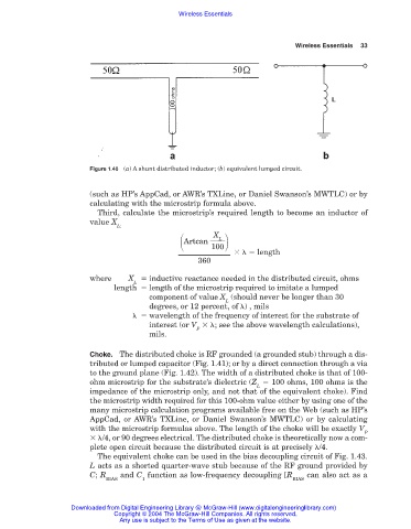
Figure 1.40 (a) A shunt distributed inductor; (b) equivalent lumped circuit.
(such as HP’s AppCad, or AWR’s TXLine, or Daniel Swanson’s MWTLC) or by
calculating with the microstrip formula above.
Third, calculate the microstrip’s required length to become an inductor of
value X
L:
Artcan
X
L
100
length
360
where X inductive reactance needed in the distributed circuit, ohms
L
length length of the microstrip required to imitate a lumped
component of value X (should never be longer than 30
L
degrees, or 12 percent, of ) , mils
wavelength of the frequency of interest for the substrate of
interest (or V ; see the above wavelength calculations),
P
mils.
Choke. The distributed choke is RF grounded (a grounded stub) through a dis-
tributed or lumped capacitor (Fig. 1.41); or by a direct connection through a via
to the ground plane (Fig. 1.42). The width of a distributed choke is that of 100-
ohm microstrip for the substrate’s dielectric (Z 100 ohms, 100 ohms is the
L
impedance of the microstrip only, and not that of the equivalent choke). Find
the microstrip width required for this 100-ohm value either by using one of the
many microstrip calculation programs available free on the Web (such as HP’s
AppCad, or AWR’s TXLine, or Daniel Swanson’s MWTLC) or by calculating
with the microstrip formulas above. The length of the choke will be exactly V
P
/4, or 90 degrees electrical. The distributed choke is theoretically now a com-
plete open circuit because the distributed circuit is at precisely /4.
The equivalent choke can be used in the bias decoupling circuit of Fig. 1.43.
L acts as a shorted quarter-wave stub because of the RF ground provided by
C; R and C function as low-frequency decoupling [R can also act as a
BIAS 1 BIAS
Downloaded from Digital Engineering Library @ McGraw-Hill (www.digitalengineeringlibrary.com)
Copyright © 2004 The McGraw-Hill Companies. All rights reserved.
Any use is subject to the Terms of Use as given at the website.