
Page 29 - Complete Wireless Design
P. 29
Wireless Essentials
28 Chapter One
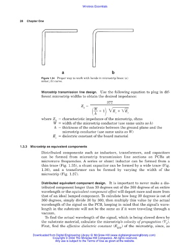
Figure 1.34 Proper way to work with bends in microstrip lines: (a)
miter; (b) curve.
Microstrip transmission line design. Use the following equation to plug in dif-
ferent microstrip widths to obtain the desired impedance:
377
Z
1 E E r
0 W
h
r
where Z characteristic impedance of the microstrip, ohms
0
W width of the microstrip conductor (use same units as h)
h thickness of the substrate between the ground plane and the
microstrip conductor (use same units as W)
E dielectric constant of the board material
r
1.3.3 Microstrip as equivalent components
Distributed components such as inductors, transformers, and capacitors
can be formed from microstrip transmission line sections on PCBs at
microwave frequencies. A series or shunt inductor can be formed from a
thin trace (Fig. 1.35), a shunt capacitor can be formed by a wide trace (Fig.
1.36), and a transformer can be formed by varying the width of the
microstrip (Fig. 1.37).
Distributed equivalent component design. It is important to never make a dis-
tributed component longer than 30 degrees out of the 360 degrees of an entire
wavelength or the equivalent component effect will depart more and more from
that of an ideal lumped component. To calculate how long 30 degrees is out of
360 degrees, simply divide 30 by 360, then multiply this value by the actual
wavelength of the signal on the PCB, keeping in mind that the signal’s wave-
length in the substrate will not be the same as if it were traveling through a
vacuum.
To find the actual wavelength of the signal, which is being slowed down by
the substrate material, calculate the microstrip’s velocity of propagation (V ).
P
First, find the effective dielectric constant (E ) of the microstrip, since, as
EFF
Downloaded from Digital Engineering Library @ McGraw-Hill (www.digitalengineeringlibrary.com)
Copyright © 2004 The McGraw-Hill Companies. All rights reserved.
Any use is subject to the Terms of Use as given at the website.