
Page 24 - Complete Wireless Design
P. 24
Wireless Essentials
Wireless Essentials 23
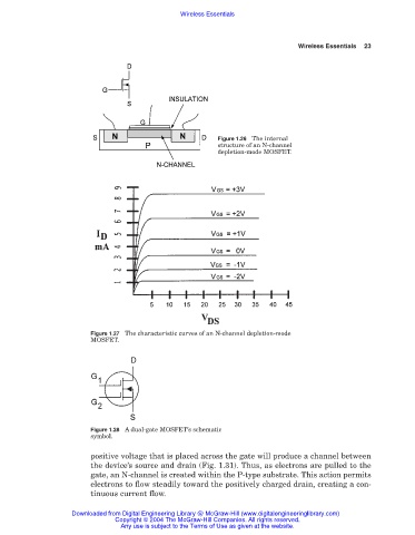
Figure 1.26 The internal
structure of an N-channel
depletion-mode MOSFET.
Figure 1.27 The characteristic curves of an N-channel depletion-mode
MOSFET.
Figure 1.28 A dual-gate MOSFET’s schematic
symbol.
positive voltage that is placed across the gate will produce a channel between
the device’s source and drain (Fig. 1.31). Thus, as electrons are pulled to the
gate, an N-channel is created within the P-type substrate. This action permits
electrons to flow steadily toward the positively charged drain, creating a con-
tinuous current flow.
Downloaded from Digital Engineering Library @ McGraw-Hill (www.digitalengineeringlibrary.com)
Copyright © 2004 The McGraw-Hill Companies. All rights reserved.
Any use is subject to the Terms of Use as given at the website.