
Page 19 - Complete Wireless Design
P. 19
Wireless Essentials
18 Chapter One
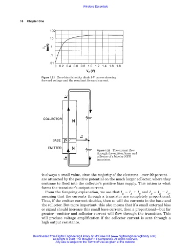
Figure 1.21 Zero-bias Schottky diode I-V curves showing
forward voltage and the resultant forward current.
Figure 1.22 The current flow
through the emitter, base, and
collector of a bipolar NPN
transistor.
is always a small value, since the majority of the electrons—over 99 percent—
are attracted by the positive potential on the much larger collector, where they
continue to flood into the collector’s positive bias supply. This action is what
forms the transistor’s output current.
From the foregoing explanation, we see that I I I and I I I ,
E B C B E C
meaning that the currents through a transistor are completely proportional.
Thus, if the emitter current doubles, then so will the currents in the base and
the collector. But more important, this also means that if a small external bias
or signal should increase this small base current, then a proportional—but far
greater—emitter and collector current will flow through the transistor. This
will produce voltage amplification if the collector current is sent through a
high output resistance.
Downloaded from Digital Engineering Library @ McGraw-Hill (www.digitalengineeringlibrary.com)
Copyright © 2004 The McGraw-Hill Companies. All rights reserved.
Any use is subject to the Terms of Use as given at the website.