
Page 16 - Complete Wireless Design
P. 16
Wireless Essentials
Wireless Essentials 15
I , the zener current required to maintain the diode within its V region
Z Z
P , the maximum approved power dissipation for the diode
D
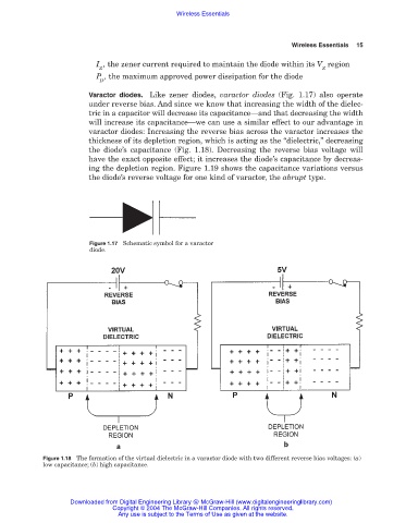
Varactor diodes. Like zener diodes, varactor diodes (Fig. 1.17) also operate
under reverse bias. And since we know that increasing the width of the dielec-
tric in a capacitor will decrease its capacitance—and that decreasing the width
will increase its capacitance—we can use a similar effect to our advantage in
varactor diodes: Increasing the reverse bias across the varactor increases the
thickness of its depletion region, which is acting as the “dielectric,” decreasing
the diode’s capacitance (Fig. 1.18). Decreasing the reverse bias voltage will
have the exact opposite effect; it increases the diode’s capacitance by decreas-
ing the depletion region. Figure 1.19 shows the capacitance variations versus
the diode’s reverse voltage for one kind of varactor, the abrupt type.
Figure 1.17 Schematic symbol for a varactor
diode.
Figure 1.18 The formation of the virtual dielectric in a varactor diode with two different reverse bias voltages: (a)
low capacitance; (b) high capacitance.
Downloaded from Digital Engineering Library @ McGraw-Hill (www.digitalengineeringlibrary.com)
Copyright © 2004 The McGraw-Hill Companies. All rights reserved.
Any use is subject to the Terms of Use as given at the website.