
Page 28 - Complete Wireless Design
P. 28
Wireless Essentials
Wireless Essentials 27
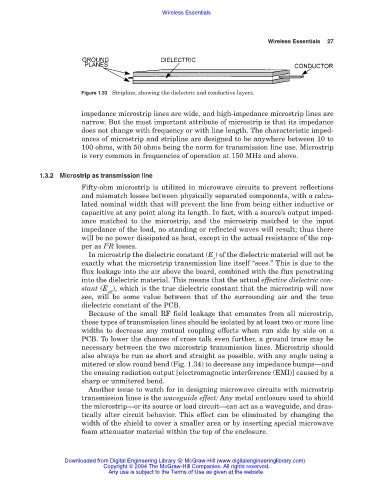
Figure 1.33 Stripline, showing the dielectric and conductive layers.
impedance microstrip lines are wide, and high-impedance microstrip lines are
narrow. But the most important attribute of microstrip is that its impedance
does not change with frequency or with line length. The characteristic imped-
ances of microstrip and stripline are designed to be anywhere between 10 to
100 ohms, with 50 ohms being the norm for transmission line use. Microstrip
is very common in frequencies of operation at 150 MHz and above.
1.3.2 Microstrip as transmission line
Fifty-ohm microstrip is utilized in microwave circuits to prevent reflections
and mismatch losses between physically separated components, with a calcu-
lated nominal width that will prevent the line from being either inductive or
capacitive at any point along its length. In fact, with a source’s output imped-
ance matched to the microstrip, and the microstrip matched to the input
impedance of the load, no standing or reflected waves will result; thus there
will be no power dissipated as heat, except in the actual resistance of the cop-
2
per as I R losses.
In microstrip the dielectric constant (E ) of the dielectric material will not be
r
exactly what the microstrip transmission line itself “sees.” This is due to the
flux leakage into the air above the board, combined with the flux penetrating
into the dielectric material. This means that the actual effective dielectric con-
stant (E ), which is the true dielectric constant that the microstrip will now
eff
see, will be some value between that of the surrounding air and the true
dielectric constant of the PCB.
Because of the small RF field leakage that emanates from all microstrip,
these types of transmission lines should be isolated by at least two or more line
widths to decrease any mutual coupling effects when run side by side on a
PCB. To lower the chances of cross talk even further, a ground trace may be
necessary between the two microstrip transmission lines. Microstrip should
also always be run as short and straight as possible, with any angle using a
mitered or slow round bend (Fig. 1.34) to decrease any impedance bumps—and
the ensuing radiation output [electromagnetic interference (EMI)] caused by a
sharp or unmitered bend.
Another issue to watch for in designing microwave circuits with microstrip
transmission lines is the waveguide effect: Any metal enclosure used to shield
the microstrip—or its source or load circuit—can act as a waveguide, and dras-
tically alter circuit behavior. This effect can be eliminated by changing the
width of the shield to cover a smaller area or by inserting special microwave
foam attenuator material within the top of the enclosure.
Downloaded from Digital Engineering Library @ McGraw-Hill (www.digitalengineeringlibrary.com)
Copyright © 2004 The McGraw-Hill Companies. All rights reserved.
Any use is subject to the Terms of Use as given at the website.