
Page 83 - Complete Wireless Design
P. 83
Modulation
82 Chapter Two
signals. Quadrature modulators have only recently become popular, after they
were integrated onto a single low-cost chip. These devices solve the problem of
imparting complex amplitude/phase information onto an RF or IF carrier.
Any part of a signal’s parameters can be modified by the quadrature modu-
lator—phase, frequency, and/or amplitude—thus can add information to an
unmodulated carrier. Simply employing a single mixer for this role would be
unacceptable, since only one parameter (such as phase for a BPSK signal)
could be modified at a time, making an efficient digital modulation scheme
infeasible.
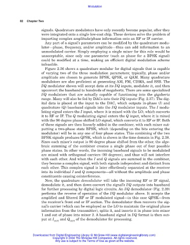
Figure 2.36 shows a quadrature modular for digital signals that is capable
of varying two of the three modulation parameters; typically, phase and/or
amplitude are chosen to generate BPSK, QPSK, or QAM. Many quadrature
modulators are also proficient at generating AM, FM, CDMA, and SSB. The
I/Q modulator shown will accept data at its I/Q inputs, modulate it, and then
upconvert the baseband to hundreds of megahertz. There are some specialized
I/Q modulators that are actually capable of functioning into the gigahertz
range. Many will also be fed by DACs into their I/Q inputs (Fig. 2.37). The dig-
ital data is placed at the input to the DAC, which outputs in-phase (I) and
quadrature (Q) baseband signals into the I/Q modulator inputs. The I modu-
lating signal enters the I input, where it is mixed with the LO, which converts
it to RF or IF. The Q modulating signal enters the Q input, where it is mixed
with the 90 degree phase shifted LO signal, which converts it to RF or IF. Both
of these signals are then linearly added in the combiner, with each mixer out-
putting a two-phase state BPSK, which (depending on the bits entering the
modulator) will be in any one of four phase states. This combining of the two
BPSK signals produces QPSK, which is shown in the time domain in Fig. 2.38.
Since each mixer’s output is 90 degree phase shifted from the other, the alge-
braic summing of the combiner creates a single phase out of four possible
phase states. In other words, the incoming baseband signals to be modulated
are mixed with orthogonal carriers (90 degrees), and thus will not interfere
with each other. And when the I and Q signals are summed in the combiner,
they become a complex signal, with both signals independent and distinct from
each other. This complex signal is later effortlessly separated at the receiver
into its individual I and Q components—all without the amplitude and phase
constituents causing cointerference.
Now, the quadrature demodulator will take the incoming RF or IF signal,
demodulate it, and then down-convert the signal’s I/Q outputs into baseband
for further processing by digital logic circuits. An I/Q demodulator (Fig. 2.39)
performs the reverse of operation of the I/Q modulator above. It accepts the
amplified and filtered RF or IF modulated signal—in this case QPSK—from
the receiver’s front end or IF section. The demodulator then recovers the sig-
nal’s carrier (which can be employed as the LO to maintain the original phase
information from the transmitter), splits it, and inserts it in phase into mixer
1 and out of phase into mixer 2. A baseband signal in I/Q format is then out-
put at I and Q of the demodulator for processing.
OUT OUT
Downloaded from Digital Engineering Library @ McGraw-Hill (www.digitalengineeringlibrary.com)
Copyright © 2004 The McGraw-Hill Companies. All rights reserved.
Any use is subject to the Terms of Use as given at the website.