
Page 82 - Complete Wireless Design
P. 82
Modulation
Modulation 81
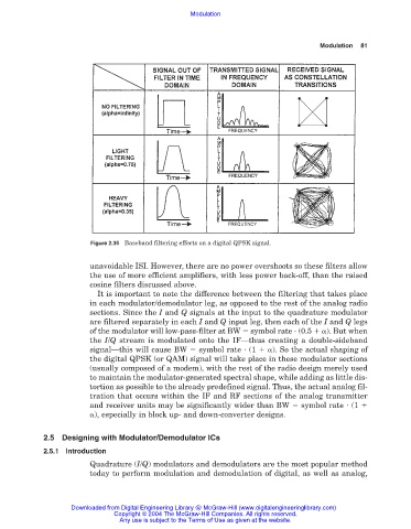
Figure 2.35 Baseband filtering effects on a digital QPSK signal.
unavoidable ISI. However, there are no power overshoots so these filters allow
the use of more efficient amplifiers, with less power back-off, than the raised
cosine filters discussed above.
It is important to note the difference between the filtering that takes place
in each modulator/demodulator leg, as opposed to the rest of the analog radio
sections. Since the I and Q signals at the input to the quadrature modulator
are filtered separately in each I and Q input leg, then each of the I and Q legs
of the modulator will low-pass-filter at BW symbol rate (0.5 ). But when
the I/Q stream is modulated onto the IF—thus creating a double-sideband
signal—this will cause BW symbol rate (1 ). So the actual shaping of
the digital QPSK (or QAM) signal will take place in these modulator sections
(usually composed of a modem), with the rest of the radio design merely used
to maintain the modulator-generated spectral shape, while adding as little dis-
tortion as possible to the already predefined signal. Thus, the actual analog fil-
tration that occurs within the IF and RF sections of the analog transmitter
and receiver units may be significantly wider than BW symbol rate (1
), especially in block up- and down-converter designs.
2.5 Designing with Modulator/Demodulator ICs
2.5.1 Introduction
Quadrature (I/Q) modulators and demodulators are the most popular method
today to perform modulation and demodulation of digital, as well as analog,
Downloaded from Digital Engineering Library @ McGraw-Hill (www.digitalengineeringlibrary.com)
Copyright © 2004 The McGraw-Hill Companies. All rights reserved.
Any use is subject to the Terms of Use as given at the website.