
Page 105 - Compression Machinery for Oil and Gas
P. 105
94 SECTION II Types of Equipment
1000
900
800
700
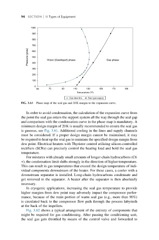
Pressure (psia) 600 Mixed (Gas/liquid) phase Gas phase
500
400
300
200
100
0
70 90 110
50 130 150 170 190
Temperature (°F)
Gas dew line Seal gas supply
FIG. 3.61 Phase map of the seal gas and 20K margin to the expansion curve.
In order to avoid condensation, the calculation of the expansion curve from
the point the seal gas enters the support system all the way through the seal gap
and comparison with the condensation curve in the phase map is mandatory. A
minimum design margin of 20K is usually recommended to ensure the seal gas
is gaseous, see Fig. 3.61. Additional cooling in the lines and supply channels
must be considered. If a proper design margin cannot be maintained, it may
be required to heat up the seal gas to maintain the specified design margin from
dew point. Electrical heaters with Thyristor control utilizing silicon-controlled
rectifiers (SCRs) can precisely control the heating load and hold the seal gas
temperature.
For mixtures with already small amounts of longer-chain hydrocarbons (C6
+), the condensation limit shifts strongly in the direction of higher temperature.
This can result in gas temperatures that exceed the design temperature of indi-
vidual components downstream of the heater. For these cases, a cooler with a
downstream separator is installed. Long-chain hydrocarbons condensate and
get removed in the separator. A heater after the separator is then absolutely
necessary.
In cryogenic applications, increasing the seal gas temperature to provide
higher margins from dew point may adversely impact the compressor perfor-
mance, because of the main portion of warm seal gas (e.g., more than 90%)
is circulated back to the compressor flow path through the process labyrinth
at the back of the impellers.
Fig. 3.62 shows a typical arrangement of the entirety of components that
might be required for gas conditioning. After passing the conditioning unit,
the seal gas gets throttled by means of the control valve and forwarded to