
Page 161 - Compression Machinery for Oil and Gas
P. 161
Integrally Geared Compressors Chapter 4 149
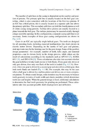
The number of split lines in the casing is dependent on the number and posi-
tion of pinions. The primary split line is usually located on the bull gear cen-
terline, which is also coincident with the locations of the first two pinions. If
an IGC has a third pinion, this is usually located in a separate split line above
the primary split line. This secondary split line can hold the fourth pinion as well
if volute casing sizing permits. Turbine-drive pinions are usually located in a
plane beneath the bull gear. The turbine pinion may be inserted axially through
a large assembly opening. In this configuration, a separate casing split line is not
necessary. Some examples of these gear casing configurations are shown in
Fig. 4.10.
Gears in an IGC are typically single helical gears. The teeth are designed
for all operating loads, including expected malfunctions like short circuits in
electric motor drivers. Depending on the inertia of bull gear and pinions,
start-up events may be the limiting case for the gear design. Some of the gearbox
design parameters—for example, number of teeth, helix angle, and material
properties—can be chosen freely in the design process, while others are the
result of calculations according to the standards such as API 613 [7], AGMA
6011 [8], and ISO 6336 [9]. These calculations also take into account whether
the gear teeth have to take loads on one or both flanks. If one gear only drives or
only gets driven, then only one flank of the teeth is loaded (Fig. 4.11A). How-
ever, when one gear is driven by a second gear and also drives a third gear, then
both tooth flanks are loaded (Fig. 4.11B). For example, this may be the case
when a bull gear is driven by a turbine pinion and drives one or more compres-
sor pinions. To obtain sound design, some iteration may be necessary to balance
tooth geometry in terms of tooth width and elastic modulus (which determines
tooth size and height). When the general design is fixed, additional calculations
to determine the final tooth geometry for grinding are performed. These calcu-
lations take into account possible shaft misalignment and deflection.
FIG. 4.10 Gear casing configurations.