
Page 159 - Compression Machinery for Oil and Gas
P. 159
Integrally Geared Compressors Chapter 4 147
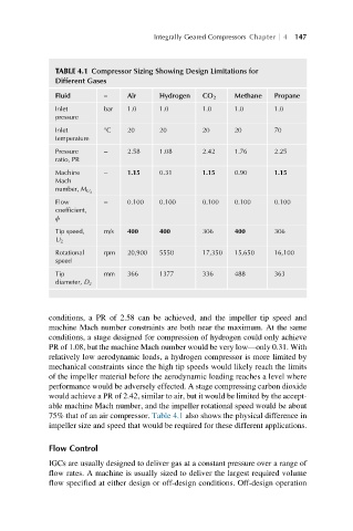
TABLE 4.1 Compressor Sizing Showing Design Limitations for
Different Gases
Fluid – Air Hydrogen CO 2 Methane Propane
Inlet bar 1.0 1.0 1.0 1.0 1.0
pressure
Inlet °C 20 20 20 20 70
temperature
Pressure – 2.58 1.08 2.42 1.76 2.25
ratio, PR
Machine – 1.15 0.31 1.15 0.90 1.15
Mach
number, M U 2
Flow – 0.100 0.100 0.100 0.100 0.100
coefficient,
ϕ
Tip speed, m/s 400 400 306 400 306
U 2
Rotational rpm 20,900 5550 17,350 15,650 16,100
speed
Tip mm 366 1377 336 488 363
diameter, D 2
conditions, a PR of 2.58 can be achieved, and the impeller tip speed and
machine Mach number constraints are both near the maximum. At the same
conditions, a stage designed for compression of hydrogen could only achieve
PR of 1.08, but the machine Mach number would be very low—only 0.31. With
relatively low aerodynamic loads, a hydrogen compressor is more limited by
mechanical constraints since the high tip speeds would likely reach the limits
of the impeller material before the aerodynamic loading reaches a level where
performance would be adversely effected. A stage compressing carbon dioxide
would achieve a PR of 2.42, similar to air, but it would be limited by the accept-
able machine Mach number, and the impeller rotational speed would be about
75% that of an air compressor. Table 4.1 also shows the physical difference in
impeller size and speed that would be required for these different applications.
Flow Control
IGCs are usually designed to deliver gas at a constant pressure over a range of
flow rates. A machine is usually sized to deliver the largest required volume
flow specified at either design or off-design conditions. Off-design operation