
Page 158 - Compression Machinery for Oil and Gas
P. 158
146 SECTION II Types of Equipment
100%
90%
Vaneless diffuser
80%
70%
Operating range: · · (m stall – m choke )/m choke 60%
50%
· 40%
30%
20%
Vaned diffuser
10%
Stage test results
0%
0.4 0.5 0.6 0.7 0.8 0.9 1.0 1.1 1.2 1.3 1.4
U2
Impeller mach number (M )
¼0.5–1.4.
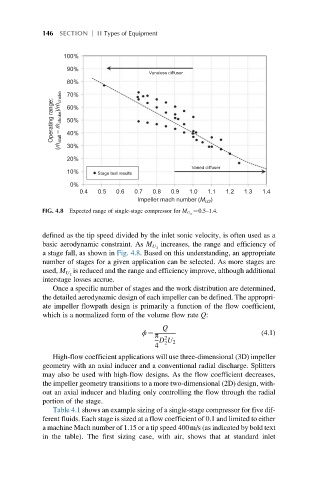
FIG. 4.8 Expected range of single-stage compressor for M U 2
defined as the tip speed divided by the inlet sonic velocity, is often used as a
increases, the range and efficiency of
basic aerodynamic constraint. As M U 2
a stage fall, as shown in Fig. 4.8. Based on this understanding, an appropriate
number of stages for a given application can be selected. As more stages are
is reduced and the range and efficiency improve, although additional
used, M U 2
interstage losses accrue.
Once a specific number of stages and the work distribution are determined,
the detailed aerodynamic design of each impeller can be defined. The appropri-
ate impeller flowpath design is primarily a function of the flow coefficient,
which is a normalized form of the volume flow rate Q:
Q
π 2
ϕ ¼ (4.1)
D U 2
2
4
High-flow coefficient applications will use three-dimensional (3D) impeller
geometry with an axial inducer and a conventional radial discharge. Splitters
may also be used with high-flow designs. As the flow coefficient decreases,
the impeller geometry transitions to a more two-dimensional (2D) design, with-
out an axial inducer and blading only controlling the flow through the radial
portion of the stage.
Table 4.1 shows an example sizing of a single-stage compressor for five dif-
ferent fluids. Each stage is sized at a flow coefficient of 0.1 and limited to either
a machine Mach number of 1.15 or a tip speed 400m/s (as indicated by bold text
in the table). The first sizing case, with air, shows that at standard inlet