
Page 153 - Compression Machinery for Oil and Gas
P. 153
Integrally Geared Compressors Chapter 4 141
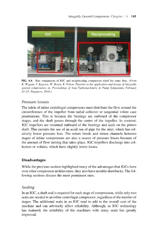
FIG. 4.6 Size comparison of IGC and reciprocating compressor sized for same duty. (From
K. Wygant, J. Bygrave, W. Bosen, R. Pelton, Tutorial on the application and design of integrally
geared compressors, in: Proceedings of Asia Turbomachinery & Pump Symposium, February
22–25, Singapore, 2016.)
Pressure Losses
The inlets of inline centrifugal compressors must distribute the flow around the
circumference of the impeller from radial collector or tangential volute case
penetrations. This is because the bearings are outboard of the compressor
stages, and the shaft passes through the center of the impeller. In contrast,
IGC impellers are mounted outboard of the bearings and seals on the pinion
shaft. This permits the use of an axial run of pipe for the inlet, which has rel-
atively lower pressure loss. The return bends and return channels between
stages of inline compressors are also a source of pressure losses because of
the amount of flow turning that takes place. IGC impellers discharge into col-
lectors or volutes, which have slightly lower losses.
Disadvantages
While the previous section highlighted many of the advantages that IGCs have
over other compressor architectures, they also have notable drawbacks. The fol-
lowing sections discuss the most prominent ones.
Sealing
In an IGC, a shaft seal is required for each stage of compression, while only two
seals are needed in an inline centrifugal compressor, regardless of the number of
stages. The additional seals in an IGC tend to add to the overall cost of the
machine and can adversely affect reliability. Although, as IGC technology
has matured, the reliability of the machines with many seals has greatly
improved.