
Page 149 - Compression Machinery for Oil and Gas
P. 149
Integrally Geared Compressors Chapter 4 137
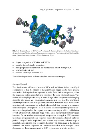
FIG. 4.2 Exploded view of IGC. (From K. Wygant, J. Bygrave, W. Bosen, R. Pelton, Tutorial on
the application and design of integrally geared compressors, in: Proceedings of Asia Turbomachin-
ery & Pump Symposium, February 22–25, Singapore, 2016.)
l simple integration of VIGVs and VDVs,
l modularity and simpler restaging,
l multiple process streams can be incorporated within a single IGC,
l smaller footprint, and
l reduced interstage pressure loss
The following sections elaborate further on these advantages.
Design Speed
The fundamental difference between IGCs and traditional inline centrifugal
compressors is that the speeds of the compressor stages can be more closely
matched to their optimal aerodynamic speeds. In an inline compressor, all of
the stages are on the same shaft and operate at the same rotational speed. This
makes achieving high efficiency in a multistage inline compressor challenging
since the later stages may be required to operate at a very low flow coefficient
where high frictional and leakage losses dominate. However, IGCs have at most
two stages of compression on a single pinion shaft that operate at a common
rotational speed. Other pinions in the machine can be designed to operate at dif-
ferent speeds optimal to the respective compressor stages, which yields better
overall efficiency at a reduced stage count. Since the optimal impeller speed
increases for each subsequent stage of compression in a typical IGC, consecu-
tive stages are positioned on a common pinion: for example, stages 1 and 2 on
pinion 1, stages 3 and 4 on pinion 2, etc. In some applications, only one stage is
mounted on a pinion to give even more flexibility on stage speed in the design;
however, this results in greater net thrust force that has to be managed. More
discussion on thrust management in IGCs is presented in a later section.