
Page 148 - Compression Machinery for Oil and Gas
P. 148
136 SECTION II Types of Equipment
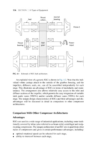
FIG. 4.1 Schematic of IGC shaft architecture.
An exploded view of a generic IGC is shown in Fig. 4.2. Note that the indi-
vidual volute casings attach to the outside of the gearbox housing, and the
impellers, diffusers, seals, etc., can all be assembled independently for each
stage. This illustrates an advantage of IGCs in terms of modularity and main-
tenance. The arrangement also allows relatively easy access to the inlet and
diffuser sections of the impeller, which permits the easy integration of variable
inlet guide vanes (VIGVs) and/or variable diffuser vanes (VDVs) for each
stage. The unique design characteristics of IGCs and their advantages and dis-
advantages will be discussed in detail in comparison to other compressor
architectures.
Comparison With Other Compressor Architectures
Advantages
IGCs are used in a wide range of industrial applications, including some tradi-
tionally covered by inline (also referred to as beam style) centrifugal and recip-
rocating compressors. The unique architecture of an IGC sets it apart from other
styles of compressors and gives it certain performance advantages, including:
l optimal rotational speed can be selected for each stage,
l ability to intercool between each stage,