
Page 152 - Compression Machinery for Oil and Gas
P. 152
140 SECTION II Types of Equipment
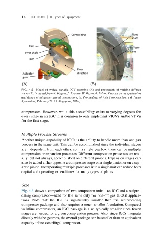
FIG. 4.5 Model of typical variable IGV assembly (A) and photograph of variable diffuser
vanes (B). (Adapted from K. Wygant, J. Bygrave, W. Bosen, R. Pelton, Tutorial on the application
and design of integrally geared compressors, in: Proceedings of Asia Turbomachinery & Pump
Symposium, February 22–25, Singapore, 2016.)
compressors. However, while this accessibility exists to varying degrees for
every stage in an IGC, it is common to only implement VIGVs and/or VDVs
for the first stage.
Multiple Process Streams
Another unique capability of IGCs is the ability to handle more than one gas
process in the same unit. This can be accomplished since the individual stages
are independent from each other, so in a single gearbox, there can be multiple
compression or expansion processes. Different compression processes are usu-
ally, but not always, accomplished on different pinions. Expansion stages can
also be added either opposite a compressor stage on a single pinion or on a sep-
arate pinion. Incorporating multiple processes into a single unit can reduce both
capital and operating expenditures for many types of plants.
Size
Fig. 4.6 shows a comparison of two compressor units—an IGC and a recipro-
cating compressor—sized for the same duty for boil-off gas (BOG) applica-
tions. Note that the IGC is significantly smaller than the reciprocating
compressor package and also requires a much smaller foundation. Compared
to inline compressors, an IGC package is also typically smaller since fewer
stages are needed for a given compression process. Also, since IGCs integrate
directly with the gearbox, the overall package can be smaller than an equivalent
capacity inline centrifugal compressor.