
Page 151 - Compression Machinery for Oil and Gas
P. 151
Integrally Geared Compressors Chapter 4 139
Effect of intercooling on compression work
(Overall PR 13:1 - air)
110%
105%
100% Intercooled
Relative shaft power 95% No intercooling
90%
85%
80%
75%
70%
1 2 3 4 5 6 7
Stages
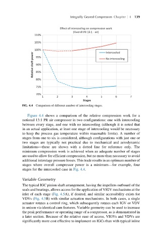
FIG. 4.4 Comparison of different number of intercooling stages.
Figure 4.4 shows a comparison of the relative compression work for a
notional 13:1 PR air compressor in two configurations: one with intercooling
between every stage, and one with no intercooling (although it is noted that
in an actual application, at least one stage of intercooling would be necessary
to keep the process gas temperature within reasonable limits). A number of
stages from one to six is considered, although configurations with just one or
two stages are typically not practical due to mechanical and aerodynamic
limitations—these are shown with a dotted line for reference only. The
minimum compression work is achieved when an adequate number of stages
are used to allow for efficient compression, but no more than necessary to avoid
additional interstage pressure losses. This trade results in an optimum number of
stages where overall compressor power is a minimum—for example, four
stages for the intercooled case in Fig. 4.4.
Variable Geometry
The typical IGC pinion shaft arrangement, having the impellers outboard of the
seals and bearings, allows access for the application of VIGV mechanisms at the
inlet of each stage (Fig. 4.5A), if desired, and similar accessibility exists for
VDVs (Fig. 4.5B) with similar actuation mechanisms. In both cases, a single
actuator rotates a control ring, which subsequently rotates each IGV or VDV
in unison via identical cam features. Variable geometry can be used to increase
the peak performance or operating range of a compressor, as is demonstrated in
a later section. Because of the relative ease of access, VIGVs and VDVs are
significantly more cost effective to implement on IGCs than with typical inline