
Page 155 - Compression Machinery for Oil and Gas
P. 155
Integrally Geared Compressors Chapter 4 143
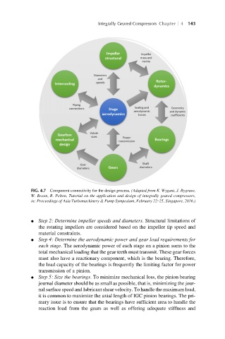
FIG. 4.7 Component connectivity for the design process. (Adapted from K. Wygant, J. Bygrave,
W. Bosen, R. Pelton, Tutorial on the application and design of integrally geared compressors,
in: Proceedings of Asia Turbomachinery & Pump Symposium, February 22–25, Singapore, 2016.)
l Step 2: Determine impeller speeds and diameters. Structural limitations of
the rotating impellers are considered based on the impeller tip speed and
material constraints.
l Step 4: Determine the aerodynamic power and gear load requirements for
each stage. The aerodynamic power of each stage on a pinion sums to the
total mechanical loading that the gear teeth must transmit. These gear forces
must also have a reactionary component, which is the bearing. Therefore,
the load capacity of the bearings is frequently the limiting factor for power
transmission of a pinion.
l Step 5: Size the bearings. To minimize mechanical loss, the pinion bearing
journal diameter should be as small as possible, that is, minimizing the jour-
nal surface speed and lubricant shear velocity. To handle the maximum load,
it is common to maximize the axial length of IGC pinion bearings. The pri-
mary issue is to ensure that the bearings have sufficient area to handle the
reaction load from the gears as well as offering adequate stiffness and