
Page 160 - Compression Machinery for Oil and Gas
P. 160
148 SECTION II Types of Equipment
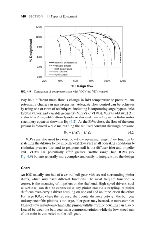
FIG. 4.9 Comparison of compressor maps with VIGV and VDV control.
may be a different mass flow, a change in inlet temperature or pressure, and
potentially changes in gas properties. Adequate flow control can be achieved
by using one or more of techniques, including incorporating stage bypass, inlet
throttle valves, and variable geometry (VIGVs or VDVs). VIGVs add swirl (C 1 )
to the inlet flow, which directly reduces the work according to the Euler turbo-
machinery equation shown in Eq. (4.2). As the IGVs close, the flow of the com-
pressor is reduced while maintaining the required constant discharge pressure:
W x ¼ U 2 C 2 U 1 C 1 (4.2)
VDVs are also used to extend low-flow operating range. They function by
matching the diffuser to the impeller exit flow state at all operating conditions to
minimize pressure loss and to postpone stall in the diffuser inlet and impeller
exit. VDVs can potentially offer greater throttle range than IGVs (see
Fig. 4.9) but are generally more complex and costly to integrate into the design.
Gears
An IGC usually consists of a central bull gear with several surrounding pinion
shafts, which may have different functions. The most frequent function, of
course, is the mounting of impellers on the shaft end. High-speed drivers, such
as turbines, can also be connected to any pinion end via a coupling. A pinion
shaft can even carry a driver coupling on one end and an impeller on the other.
For large IGCs, where the required shaft center distance between the bull gear
and any one of the pinions is too large, idler gears may be used. In more complex
trains of several turbomachines, the pinion with the turbine coupling can also be
located between the bull gear and a compressor pinion while the low-speed part
of the train is connected to the bull gear.