
Page 170 - Compression Machinery for Oil and Gas
P. 170
158 SECTION II Types of Equipment
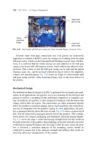
FIG. 4.20 Horizontally split bull gear casing and volute mounting flanges. (Courtesy Voith.)
External loads from pipe connections and even gravity are particularly
important to consider with IGCs since the casings are overhung from the main
bull gear casing, which can develop significant bending moment loads. Further-
more, it is common that the volute casings are only attached to the bull gear
casing at the lower half (180 degrees sector), which reduces the allowed exter-
nal loads. This is done so that the bull gear casing can be split and the pinion
bearings, seals, etc., can be accessed without having to remove the impellers,
volutes, and attached piping. Fig. 4.20 shows an image of a horizontally split
bull gear casing and the volute mounting flanges only on the lower halves of
the pinions.
Mechanical Design
The detailed mechanical design of an IGC is optimized for each particular appli-
cation. In all applications, the gearbox serves as a housing for the bull gear and
pinions as well as a mounting for the individual compressor or expander cas-
ings. In addition, the gearbox is often designed to integrate with the intercooler
casings and/or lube oil system. The intercoolers are often positioned directly
below the gearbox to minimize piping, and on small machines, the cooler hous-
ing may be integrated with the gearbox casting. In some applications, the gear-
box is packaged directly above the lube oil tank. Fig. 4.21 shows a typical small
IGC with the intercoolers packaged directly below the gearbox. This configu-
ration allows for compact packaging and minimizes interstage piping lengths.
Fig. 4.21 shows the stage 1 volute discharging straight down into the cooler on
the right-hand side of the gearbox, then returning on the left vertically out of the
cooler before turning 90 degrees into the stage 2 inlet. In cases where the gear-
box is elevated, a structural analysis of the mounting system should be
conducted to ensure that it has adequate strength and stiffness that would not
adversely affect the rotordynamics of the system.