
Page 171 - Compression Machinery for Oil and Gas
P. 171
Integrally Geared Compressors Chapter 4 159
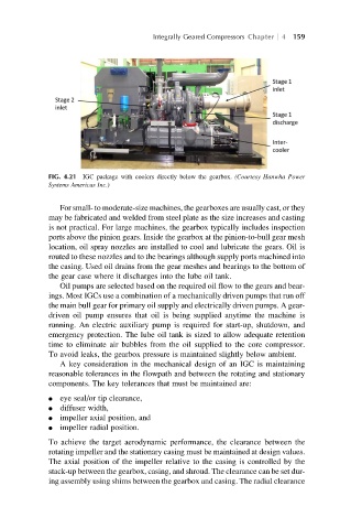
FIG. 4.21 IGC package with coolers directly below the gearbox. (Courtesy Hanwha Power
Systems Americas Inc.)
For small- to moderate-size machines, the gearboxes are usually cast, or they
may be fabricated and welded from steel plate as the size increases and casting
is not practical. For large machines, the gearbox typically includes inspection
ports above the pinion gears. Inside the gearbox at the pinion-to-bull gear mesh
location, oil spray nozzles are installed to cool and lubricate the gears. Oil is
routed to these nozzles and to the bearings although supply ports machined into
the casing. Used oil drains from the gear meshes and bearings to the bottom of
the gear case where it discharges into the lube oil tank.
Oil pumps are selected based on the required oil flow to the gears and bear-
ings. Most IGCs use a combination of a mechanically driven pumps that run off
the main bull gear for primary oil supply and electrically driven pumps. A gear-
driven oil pump ensures that oil is being supplied anytime the machine is
running. An electric auxiliary pump is required for start-up, shutdown, and
emergency protection. The lube oil tank is sized to allow adequate retention
time to eliminate air bubbles from the oil supplied to the core compressor.
To avoid leaks, the gearbox pressure is maintained slightly below ambient.
A key consideration in the mechanical design of an IGC is maintaining
reasonable tolerances in the flowpath and between the rotating and stationary
components. The key tolerances that must be maintained are:
l eye seal/or tip clearance,
l diffuser width,
l impeller axial position, and
l impeller radial position.
To achieve the target aerodynamic performance, the clearance between the
rotating impeller and the stationary casing must be maintained at design values.
The axial position of the impeller relative to the casing is controlled by the
stack-up between the gearbox, casing, and shroud. The clearance can be set dur-
ing assembly using shims between the gearbox and casing. The radial clearance