
Page 356 - Compression Machinery for Oil and Gas
P. 356
Drivers Chapter 7 341
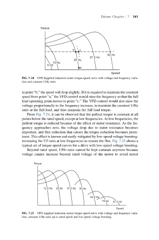
Torque
b
c
50 Hz
37.5 Hz
25 Hz
10 Hz
5 Hz
a
Speed
FIG. 7.24 VFD Supplied induction motor torque-speed curve with voltage and frequency varia-
tion and constant V/Hz ratio.
in point “b,” the speed will drop slightly. If it is required to maintain the constant
speed from point “a,” the VFD control would raise the frequency so that the full
load operating point moves to point “c.” The VFD control would also raise the
voltage proportionally to the frequency increase, to maintain the constant V/Hz
ratio at the full load, and thus maintain the full load torque.
From Fig. 7.24, it can be observed that the pullout torque is constant at all
points below the rated speed, except at low frequencies. At low frequencies, the
pullout torque is reduced because of the effect of stator resistance. As the fre-
quency approaches zero, the voltage drop due to stator resistance becomes
important, and flux reduction that causes the torque reduction becomes prom-
inent. This effect is known and easily mitigated by low-speed voltage boosting:
increasing the V/f ratio at low frequencies to restore the flux. Fig. 7.25 shows a
typical set of torque-speed curves for a drive with low-speed voltage boosting.
Beyond rated speed, V/Hz ratio cannot be kept constant anymore because
voltage cannot increase beyond rated voltage of the motor to avoid motor
Torque
12.5 Hz 25 Hz 37.5 Hz
50 Hz
62.5 Hz
75 Hz
87.5 Hz
Speed
FIG. 7.25 VFD supplied induction motor torque-speed curve with voltage and frequency varia-
tion, constant V/Hz ratio up to rated speed and low-speed voltage boosting.