
Page 355 - Compression Machinery for Oil and Gas
P. 355
340 SECTION II Types of Equipment
Filter takes the DC waveform from rectifier and provides almost pure linear
DC. Energy storage is used to support instantaneous energy balance. If with bal-
anced three-phase load, the total power remains constant from instant to instant
and with the ideal converter, the energy storage would not be required. In prac-
tice, converters require energy storage to store sufficient energy to supply the
motor during the brief intervals when load power is greater than the input
power. Capacitors and inductors are used for energy storage.
Inverter inverts the DC power back to AC through a set of electronic
switches (MOSFET (metal-oxide semiconductor field-effect transistor), IGBT
(insulated-gate bipolar transistor), IGCT (integrated gate-commutated thyris-
tor), GTO (gate turn-off thyristor), etc.). These switches, by opening and closing
at certain speeds and durations, can invert DC and recreate output currents and
voltage waveforms that mimic sinusoidal AC waveforms. The motor is then
supplied from the output of the inverter.
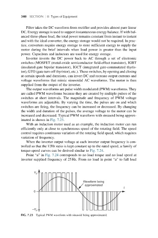
The output waveforms are pulse width modulated (PWM) waveforms. They
are called PWM waveforms because they are created by multiple pulses of the
switches at short intervals. The magnitude and frequency of PWM voltage
waveforms are adjustable. By varying the time, the pulses are on and which
switches are firing, the frequency can be increased or decreased. By changing
the width and duration of the pulses, the average voltage to the motor can be
increased and decreased. Typical PWM waveform with sinusoid being approx-
imated is shown in Fig. 7.23.
With an induction motor used as an example, the induction motor can run
efficiently only at close to synchronous speed of the rotating field. The speed
control requires continuous variation of the rotating field speed, which requires
variation of frequency.
When the inverter output voltage at each inverter output frequency is con-
trolled so that the V/Hz ratio is kept constant up to the rated speed, a family of
torque-speed curves can be derived similar to Fig. 7.24.
Point “a” in Fig. 7.24 corresponds to no load torque and no load speed at
inverter supplied frequency of 25Hz. From no load in point “a” to full load
Y d
Waveform being
t
approximated
0
–Y d
FIG. 7.23 Typical PWM waveform with sinusoid being approximated.