
Page 354 - Compression Machinery for Oil and Gas
P. 354
Drivers Chapter 7 339
When motors are supplied directly from the power network, the supply
power frequency is constant, while voltage and current change during motor
starting. During motor acceleration to synchronous speed (synchronous motors)
or close to synchronous speed (induction motors), the current would initially
rise to multiple times the rated current and cause voltage drop. Lower voltage
while supply frequency is constant means lower V/Hz ratio and lower flux
which affects the torque. Once the motor accelerates, the voltage recovers to
close to rated value and the torque available at the motor shaft is at the rated
value. The speed of the motor is then constant and synchronous (synchronous
motors) or close to synchronous (induction motors). With motors connected
directly to power network, the speed is dictated by the fixed network frequency
and cannot be controlled. To manage the speed when necessary, additional
mechanical systems are used: dampers, valves, gear boxes, brakes, etc. Mechan-
ical systems reduce the overall system efficiency. In addition, as explained pre-
viously, induction motors consume reactive power, so maintaining the power
factor may be a challenge with induction motors. Synchronous motors do not
cause issues with the power factor, they can actually help.
There are four categories of challenges with motors connected directly to the
power supply network: high starting current, torque control, speed control, and
power factor (only with the induction motors). One of the effective ways to
address the challenges is to use VFDs. When VFDs are used, the drive is sup-
plied from the power network, and the motor is supplied from the drive.
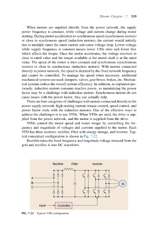
VFDs control the motor speed and motor torque by controlling the fre-
quency and magnitude of voltages and currents supplied to the motor. Each
VFD has three sections: rectifier, filter with energy storage, and inverter. Typ-
ical conceptual configuration is shown in Fig. 7.22.
Rectifier takes the fixed frequency and magnitude voltage sinusoid from the
grid and rectifies it into DC waveform.
Rectifier Filter Inverter
A
B
M
C
Input Controller
FIG. 7.22 Typical VFD configuration.