
Page 350 - Compression Machinery for Oil and Gas
P. 350
Drivers Chapter 7 335
Stator magnetic field rotation
Dotted line -
C
unstable
N S
B operation
h
A
m
d
Magnetic
flux in
Electrical
air-gap degrees
d
90°
0° 180°
32°
S'
S N
Rotor
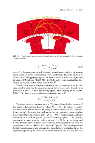
FIG. 7.21 Synchronous motor operation in synchronism: at full load (example 32 degrees) and at
no load (0 degree).
r ffiffiffiffiffiffiffiffiffiffiffiffi
35;200 P r f
f n ¼ 2 (7.7)
n WK
where f n is the undamped natural frequency in cycles/min, n is the synchronous
speed in rpm, P r is the synchronizing torque coefficient, this is the stiffness of
the electrical field applying torque to the rotor to restore it to the neutral position
in units of KW/rad (see NEMA MG1 21.36.2), and f is the electrical line fre-
2
2
quency in Hz, WK is the inertia in units lbs-ft .
The electrical natural frequency obviously must be separate from the run-
ning speed in order for the current pulsation to be below 66%. Usually, it is
between 0.5 and 0.75 times the running speed. Also referring to the NEMA
MG1 21.38, there is a term called the compressor factor C.
2
0:746 WK n 4
C ¼ (7.8)
P r f 108
Therefore, the term compressor factor (C) gives a dimensionless measure of
the inertia in the motor and driven system. At C ¼9.24, the system is in elec-
trical resonance and the natural frequency is proportional to 1/C1/2. Generally
for the multiple throw machine such as a six-throw, satisfactory current pulsa-
tion will normally be achieved at C ¼20 (f n ¼0.68 running speed) and for a
two-throw at C ¼30 or greater (f n ¼0.55 running speed). It is typically
acceptable to have a motor with minimum C ¼20 for a two-throw and
C ¼15 for four-throw or more. Any additional inertia required will be in the
compressor or can be added to the compressor flywheel. The current pulsation
for both induction and synchronous motors should always be checked during the
engineering phase by the motor manufacturer using the full load and part load