
Page 402 - Compression Machinery for Oil and Gas
P. 402
380 SECTION III Applications
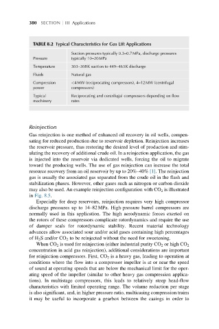
TABLE 8.2 Typical Characteristics for Gas Lift Applications
Suction pressures typically 0.3–0.7MPa, discharge pressures
Pressure typically 10–20MPa
Temperature 303–308K suction to 449–463K discharge
Fluids Natural gas
Compression <4MW (reciprocating compressors), 4–12MW (centrifugal
power compressors)
Typical Reciprocating and centrifugal compressors depending on flow
machinery rates
Reinjection
Gas reinjection is one method of enhanced oil recovery in oil wells, compen-
sating for reduced production due to reservoir depletion. Reinjection increases
the reservoir pressure, thus restoring the desired level of production and stim-
ulating the recovery of additional crude oil. In a reinjection application, the gas
is injected into the reservoir via dedicated wells, forcing the oil to migrate
toward the producing wells. The use of gas reinjection can increase the total
resource recovery from an oil reservoir by up to 20%–40% [1]. The reinjection
gas is usually the associated gas separated from the crude oil in the flash and
stabilization phases. However, other gases such as nitrogen or carbon dioxide
may also be used. An example reinjection configuration with CO 2 is illustrated
in Fig. 8.5.
Especially for deep reservoirs, reinjection requires very high compressor
discharge pressures up to 14–82MPa. High-pressure barrel compressors are
normally used in this application. The high aerodynamic forces exerted on
the rotors of these compressors complicate rotordynamics and require the use
of damper seals for rotordynamic stability. Recent material technology
advances allow associated sour and/or acid gases containing high percentages
of H 2 S and/or CO 2 to be reinjected without the need for sweetening.
When CO 2 is used for reinjection (either industrial purity CO 2 or high CO 2
concentration in acid gas reinjection), additional considerations are important
for reinjection compressors. First, CO 2 is a heavy gas, leading to operation at
conditions where the flow into a compressor impeller is at or near the speed
of sound at operating speeds that are below the mechanical limit for the oper-
ating speed of the impeller (similar to other heavy gas compression applica-
tions). In multistage compressors, this leads to relatively steep head-flow
characteristics with limited operating range. The volume reduction per stage
is also significant, and, in higher pressure ratio, multicasing compression trains
it may be useful to incorporate a gearbox between the casings in order to